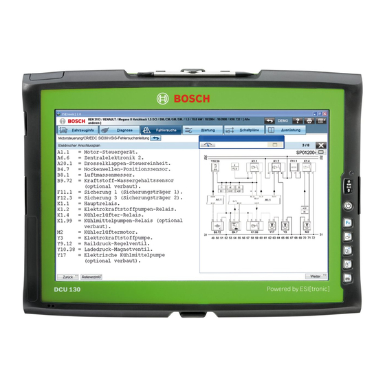
Summary of Contents for Bosch DCU 130
- Page 1 DCU 130 de Instandsetzungsanleitung en Servicing instructions Systemtester System tester 1 689 975 217 2011-06-07...
-
Page 2: Table Of Contents
2 | DCU 130 | Inhaltsverzeichnis Verwendete Symbolik In der Dokumentation Auf dem Produkt Benutzerhinweise Sicherheitshinweise Zielgruppe Übersicht Aufbau Bedienelemente Anschlüsse 3.2.1 Linke Seite 3.2.2 Rechte Seite Interne Komponenten Hilfsmittel Configuration Center ELO Touchscreen Fehlersuche Selbsttätige Abschaltung Defekter Tragegriff Defekte Abdeckklappe... -
Page 3: Verwendete Symbolik
Benutzer oder umstehende Personen hin. Zusätzlich zu Bosch Test Equipment". Diese sind vor Inbetriebnah- beschreiben Warnhinweise die Maßnahmen zur Vermei- me, Anschluss und Bedienung von DCU 130 sorgfältig dung dieser Gefahren. Eine entscheidende Bedeutung durchzulesen und zwingend zu beachten. -
Page 4: Übersicht Aufbau
4 | DCU 130 | Übersicht Aufbau Übersicht Aufbau Anschlüsse Bedienelemente 3.2.1 Linke Seite 1 USB-Schacht (vertieft, z. B. für USB-Stick), max. 0,5 A 2 USB-Anschlüsse, max. 2 A 3 Netzwerkanschluss RJ-45 (LAN) 4 Netzteilanschluss (19 Volt DC) 3.2.2 Rechte Seite 1 Kamera 2 Taststifthalterung 3 LCD-Anzeige mit Touchscreen 4 Akku (Batterie 2) 5 LEDs 6 Ein-/Aus-Taste 7 Fronttasten 1 Akkuschacht (Batterie 2) 8 Akku (Batterie 1) 2 Kopfhöreranschluss... -
Page 5: Interne Komponenten
Übersicht Aufbau | DCU 130 | 5 DCU 130 | 5 Interne Komponenten 1 Taststifthalterung 2 Tragegriff 3 Lüfterunterboden 4 Abdeckklappe 5 Grundrahmen Robert Bosch GmbH 1 689 975 217 2011-06-07... -
Page 6: Hilfsmittel
6 | DCU 130 | Hilfsmittel Hilfsmittel Configuration Center Die Funktionen des "Configuration Center" sind in der Betriebsanleitung beschrieben. Das "Configu- ration Center" ist die zentrale Anwendung, die den gesammelten Zugriff auf die Konfigurationstools ermöglicht: Batterie Informations & Diagnose Tool... -
Page 7: Fehlersuche
Fehlersuche | DCU 130 | 7 DCU 130 | 7 Fehlersuche Selbsttätige Abschaltung Mögliche Ursache Folge Abhilfe Kapitel Tablet-PC schaltet aufgrund von Defekt Tablet-PC defekt. Tablet-PC tauschen. auf Mainboard ab. Tablet-PC schaltet im Betrieb über Netz- Netzteil defekt. Netzteil tauschen. -
Page 8: Instandsetzung
8 | DCU 130 | Instandsetzung Instandsetzung Akku Wichtige Hinweise Akkus sind einzeln als Ersatzteil erhältlich und kön- nen in beiden Einschüben verwendet werden. ESD-Handhabungshinweise finden Sie in EDIS, alle Ersatzteile in der Ersatzteilliste 1 689 973 343. Ladezustand prüfen 1. Anwendung "Batterie Informations &... -
Page 9: Lüfterunterboden
Instandsetzung | DCU 130 | � DCU 130 | � | � Lüfterunterboden 5. Ladezustand des Akku über die Taste ablesen. Die Lüfter sind im Lüfterunterboden integriert. Aus diesem Grund werden keine einzelnen Lüfter ge- tauscht, sondern der komplette Lüfterunterboden. -
Page 10: Tragegriff
10 | DCU 130 | Instandsetzung Tragegriff Abdeckklappen Demontage Die Abdeckklappen sind als Ersatzteil-Teilesatz be- ¶ Schrauben des Tragegriffs (1) entfernen. stellbar. Wir empfehlen – insbesondere bei alters- bedingtem Verschleiß – den kompletten Teilesatz zu tauschen. Demontage 1. Schrauben des Tragegriffs (1) entfernen. -
Page 11: Taststifthalterung
Instandsetzung | DCU 130 | 11 DCU 130 | 11 | 11 Taststifthalterung Demontage 1. Schrauben des Tragegriffs (2) entfernen. 2. Tragegriff entfernen. 3. Schrauben des Lüfterunterbodens (3) entfernen. 4. Lüfterunterboden entfernen. 5. Schrauben der Taststifthalterung (1) entfernen. Komponente tauschen 1. Alte Taststifthalterung entfernen. - Page 12 12 | DCU 130 | Contents Symbols used In the documentation On the product User information Safety instructions Target group Design overview Controls Connections 3.2.1 Left side 3.2.2 Right side Internal components Test aid Configuration Center ELO Touchscreen Trouble-shooting Automatic disconnection...
-
Page 13: Symbols Used
The signal word has a crucial importance. It nection and operation of the DCU 130 and must always indicates the probability of occurrence and the severity be followed. -
Page 14: Design Overview
14 | DCU 130 | Design overview Design overview Connections Controls 3.2.1 Left side 1 USB slot (recessed, e.g. for USB stick) 2 USB ports 3 RJ-45 network connection (LAN) 4 Power supply unit connection (19 Volt DC) 3.2.2 Right side 1 Kamera 2 Pen holder 3 LCD with touch screen 4 Akku (Battery 2) 5 LEDs 6 On/Off key 7 Front keys... -
Page 15: Internal Components
Design overview | DCU 130 | 15 Internal components 1 Pen holder 2 Handle 3 Fan housing 4 Protective cap 5 Basic housing Robert Bosch GmbH 1 689 975 217 2011-06-07... -
Page 16: Test Aid
16 | DCU 130 | Test aid Test aid Configuration Center The functions of the "Configuration Center" are de- scribed in the operating instructions. The "Configu- ration Center" is the central application permitting collective access to the configuration tools: Batterie information & diagnosis tool... -
Page 17: Trouble-Shooting
Trouble-shooting | DCU 130 | 17 Trouble-shooting Automatic disconnection Possible cause Consequences Remedy Chapter Tablet PC switches off on account of de- Defect Tablet PC. Replace Tablet PC. fect mainboard. Tablet PC switches off automatically in Defect power supply unit. -
Page 18: Repairs
18 | DCU 130 | Repairs Repairs Battery Important information Batteries are available separately as a spare part and can be applied in both insertions. ESD handling instructions can be found in EDIS and all spare parts are in the spare parts Test charge state list 1 689 973 315. -
Page 19: Fan Housing
Repairs | DCU 130 | 1� Fan housing 4. Read off charge state of the battery by pressing the button (1). The fans are integrated in the fan housing. That's why no separate fans are exchanged, but the com- plete fan housing. -
Page 20: Handle
20 | DCU 130 | Repairs Handle Protectic caps Dismantling The protective caps are orderable as a spare part ¶ Remove the screws from the handle (1). kit. We recommend to exchange the complete kit of parts particularly with old-conditional wear. -
Page 21: Pen Holder
Repairs | DCU 130 | 21 Pen holder Dismantling 1. Remove the screws from the handle (2). 2. Remove the handle. 3. Remove the screws from the ventilation housing (3). 4. Remove the ventilation housing. 5. Remove the screws from the pen holder (1). - Page 22 Robert Bosch GmbH Diagnostics Franz-Oechsle-Straße 4 73207 Plochingen DEUTSCHLAND www.bosch.com bosch.prueftechnik@bosch.com 1 689 975 217 | 2011-06-07...


