Sign In
Upload
Manuals
Brands
Bosch Manuals
Controller
Rexroth IndraDrive M
Bosch Rexroth IndraDrive M Manuals
Manuals and User Guides for Bosch Rexroth IndraDrive M. We have
2
Bosch Rexroth IndraDrive M manuals available for free PDF download: Applications Manual, Project Planning Manual
Bosch Rexroth IndraDrive M Applications Manual (153 pages)
Integrated Safety Technology 'Safe Torque Off' (as of MPx-16)
Brand:
Bosch
| Category:
DC Drives
| Size: 8.03 MB
Table of Contents
Table of Contents
4
1 Introduction
8
About this Documentation
8
Documentations
10
Drive Systems, System Components
10
Motors
10
Gearboxes
11
Cables
11
Firmware
11
2 Important Directions for Use
14
Appropriate Use
14
Introduction
14
Areas of Use and Application
14
Inappropriate Use
15
3 Safety Instructions for Electric Drives and Controls
16
Definitions of Terms
16
General Information
17
Using the Safety Instructions and Passing Them on to Others
17
Requirements for Safe Use
17
Hazards by Improper Use
18
Instructions with Regard to Specific Dangers
19
Protection against Contact with Electrical Parts and Housings
19
Protective Extra-Low Voltage as Protection against Electric Shock
20
Protection against Dangerous Movements
21
Protection against Electromagnetic and Magnetic Fields During Operation and Mounting
22
Protection against Contact with Hot Parts
23
Protection During Handling and Mounting
23
Battery Safety
23
Protection against Pressurized Systems
24
Explanation of Signal Words and the Safety Alert Symbol
25
4 System Overview
26
Introduction
26
Motivation and Objectives
26
Conceptual Overview
27
Risk Assessment
27
Product Presentation
29
What Is "Integrated Safety Technology
29
Integrated Safety Technology as Indradrive Platform Solution
30
Safety-Relevant Standards and Regulations
40
General Information
40
Standards Relevant to Components
40
Standards Relevant to Machinery
40
EC Directives
41
Overview of Functions and Characteristics
41
Characteristics of Integrated Safety Technology
41
Supported Safety Technology Functions
42
Performance
42
Safety Characteristics of the Safety System
43
Introduction
43
Optional Safety Technology Modules "L3" / "L4
44
Calculating the Total PFH Value of a Safety Zone
45
5 Functional Principle of Integrated Safety Technology
46
Basic Functions
46
Overview
46
Dynamization
47
6 Integrated Safety Functions
52
Overview of Safety Functions
52
General Information
52
Classification of Safety Functions
52
Safety Functions in Special Mode "Safe Standstill
53
Safe Torque off (STO)
53
Safe Brake Control (SBC)
57
7 Examples of Application
62
Examples of Application for Indradrive Cs, Indradrive C and Indradrive M
62
STO and SBC Functions ("L4" Only) When Selected by Means of Passive Safety Units
62
STO and SBC Functions ("L4" Only) When Selected by Means of Active Safety Units
64
Safe Stop 1 (Emergency Stop)" Function with "L3"/"L4" Option
67
Zone Setup
68
Examples of Application for Indradrive MI
68
Single-Channel Selection
68
Central Selection at KCU
71
Distributed Selection at KSM02 / KMS02
75
Zone Setup
78
Mixed Operation of Optional Safety Technology Modules "L2" and "L3"/"L4
81
Mixed Operation of Optional Safety Technology Modules "L2" and "L3"/"L4" at an Active Safety Unit
81
Mixed Operation of Optional Safety Technology Modules "L2" and "L3"/"L4" at a Passive Safety Unit
83
8 Commissioning the Safety Technology
86
Safety Instruction
86
Prerequisites for Using Integrated Safety Technology
86
General Information
86
Required Drive Firmware
87
Required Controller Configuration
87
Required Motors and Measuring Systems
89
Allowed Motor Holding Brakes
89
Required Commissioning Tools
90
Checks before Initial Commissioning
90
Commissioning Procedure
90
Indradrive Cs: Commissioning the "Safe Torque Off" and "Safe Brake Control" Functions (Optional Safety Technology Modules "L3"/"L4")
90
Indradrive MI: Commissioning the "Safe Torque Off" Function (Optional Safety Technology Mod- Ule "L3")
94
Indradrive C, Indradrive M and Indradrive ML: Commissioning the "Safe Torque Off" Function (Optional Safety Technology Module "L3")
97
Control Unit Requirements
99
9 Notes on Troubleshooting
100
Introduction
100
Diagnostic System
100
General Information
100
Diagnostic Messages of Integrated Safety Technology
101
Overview
101
Status Information of Integrated Safety Technology
101
Behavior in the Case of Non-Fatal Safety Technology Errors (F3Xxx)
102
Behavior in the Case of Fatal Errors (F8Xxx)
103
Removing Malfunctions, Maintenance Measures, Deactivating the Motors
104
Replacing Drive Components
104
General Information
104
Replacing the Motor
104
Replacing the Brake
105
Replacing Drive Components of Indradrive ML
105
Replacing the Controller
107
10 Decommissioning Drive Components
112
11 Declarations of Conformity
114
Indradrive Cs (HCS01)
115
Indradrive M / Indradrive C (HCS, HMS)
117
Indradrive MI (KSM02, KMS02)
119
Indradrive ML (HMU05)
121
12 Project Planning
122
Indradrive C / Indradrive M and Indradrive ML
122
X49, Optional Safety Technology Safe Torque off
122
Indradrive Cs
122
X49, Optional Safety Technology L3 or L4
122
X6, Motor Temperature Monitoring and Motor Holding Brake
123
Indradrive MI
126
KCU02 Connection Points
126
KSM02 Connection Points
129
KMS02 Connection Points
137
Connectors and Cables for Safety Technology
139
E-Stop Function
140
Safety Zones
142
Technical Data of Inputs and Outputs
144
Digital Inputs (Safety Technology L Options)
144
Digital Outputs (Safety Technology L Options)
145
13 Service and Support
146
Index
148
Advertisement
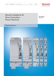
Bosch Rexroth IndraDrive M Project Planning Manual (120 pages)
Drive Controllers, Power Sections
Brand:
Bosch
| Category:
Controller
| Size: 4.79 MB
Table of Contents
Table of Contents
3
1 Introduction
7
About this Documentation
7
Purpose of Documentation
7
Introducing the Devices
8
Features and Fields of Appliction
8
Basic Structure
9
Drive System
10
Tests and Certifications
11
2 Important Directions for Use
13
Appropriate Use
13
Introduction
13
Areas of Use and Application
14
Inappropriate Use
14
3 Safety Instructions for Electric Drives and Controls
15
Introduction
15
Explanations
15
Hazards by Improper Use
16
General Information
17
Protection against Contact with Electrical Parts
19
Protection against Electric Shock by Protective Low Voltage (PELV)
20
Protection against Dangerous Movements
21
Protection against Magnetic and Electromagnetic Fields During Operation and Mounting
23
Protection against Contact with Hot Parts
24
3.10 Protection During Handling and Mounting
24
3.11 Battery Safety
25
3.12 Protection against Pressurized Systems
25
4 Identifying and Checking the Delivered Components
27
Delivery of Components
27
Packaging
27
Accompanying Documents
27
Scope of Delivery
27
Overview
27
Checking the Delivered Components
27
Component Designation
28
Device Types
29
Type Code
29
5 Transport and Storage
31
Transporting the Devices
31
Conditions
31
Storing the Devices
31
In Case of Long Storage Periods
31
6 Mechanical Mounting
33
Mounting Conditions
33
Ambient and Operating Conditions
33
Duty Capacity
34
Mechanical Technical Data
36
Dimensions
36
Weight
43
Installation Orientation
43
Arrangement of Components in the Control Cabinet
44
Cooling and Cooling Units
46
Power Dissipation
46
Power Dissipation of Power Section
46
Mounting Cooling Units
53
7 Electrical Installation
55
General Information
55
10 Rules for EMC-Correct Installation of Drives
56
Electrical Data
58
Power Section (HMS01.1N-W0020, HMD01.1N-W0012
58
Power Section (HMS01.1N-W0036
60
Power Section (HMS01.1N-W0150
62
Control Voltage
64
Drive System - Overview
65
Connecting Cables and Rails
66
Complete Connection Diagram
66
Connections on Power Section
67
Control Voltage (+24 V, 0 V)
73
DC Bus (L+, L-)
74
X5, Motor Connection (1, 2, 3, Ground)
75
Ground Connection, Power Supply Unit and Neighboring Device
79
X1, Bus Module
80
X6, Motor Temperature Monitoring and Motor Holding Brake
81
XS1, Shield Connection
84
Touch Guard
85
Cutouts
85
Mounting
86
8 Replacing Devices
87
General Information
87
How to Proceed When Replacing Devices
87
Replacing the Drive Controller
87
Replacing the Motor
88
Replacing Cables
88
Fault Report
90
9 Disposal and Environmental Protection
93
Disposal
93
Products
93
Packaging Materials
93
Environmental Protection
93
No Release of Hazardous Substances
93
Materials Contained in the Products
93
Recycling
94
10 Appendix
95
Shielding Plate for Shield Connection of the Motor Cable
95
10.2 Connection of Supply Unit by Wires
105
Supply Unit to the Left of the Drive Controller
105
Supply Unit to the Right of the Drive Controller
106
10.3 Stacked Drive Controllers
107
Anticlockwise Cable Routing
107
Clockwise Cable Routing
108
11 Service & Support
109
11.1 Helpdesk
109
11.2 Service-Hotline
109
11.3 Internet
109
Vor der Kontaktaufnahme
109
11.5 Kundenbetreuungsstellen
110
Sales & Service Facilities
110
Advertisement
Related Products
Bosch Rexroth CKL Series
Bosch Rexroth VT-VPCD Series
Bosch Rexroth GTM Series
Bosch Rexroth EcoDrive 03
Bosch Rexroth ctrl CORE
Bosch rexroth CytroForce-M
Bosch rexroth ctrlX CORE
Bosch rexroth ctrlX COREX-C
Bosch rexroth ctrlX COREX-M
Bosch rexroth CHC
Bosch Categories
Dishwasher
Washer
Oven
Power Tool
Dryer
More Bosch Manuals
Login
Sign In
OR
Sign in with Facebook
Sign in with Google
Upload manual
Upload from disk
Upload from URL