Sign In
Upload
Manuals
Brands
Dalsa Manuals
Digital Camera
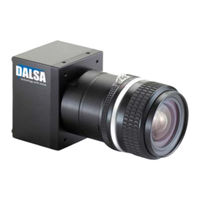
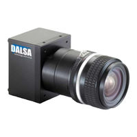
spyder SG-10-02k80
Dalsa spyder SG-10-02k80 Manuals
Manuals and User Guides for Dalsa spyder SG-10-02k80. We have
2
Dalsa spyder SG-10-02k80 manuals available for free PDF download: User Manual
Dalsa spyder SG-10-02k80 User Manual (119 pages)
Gige Spyder 3 Camera GigE Dual Line Scan Camera
Brand:
Dalsa
| Category:
Digital Camera
| Size: 1.32 MB
Table of Contents
Table of Contents
3
Contents
3
Gige Camera
5
Chapter Contents
5
Camera Highlights
6
Features
6
Programmability
6
Description
6
Applications
6
Camera Performance Specifications
7
Models
7
Image Sensor
10
Sensitivity Mode and Pixel Readout
10
Sensor Shift Direction
12
Responsivity
13
Derating Curves
13
2 Setting up the Camera
17
Installation Overview
18
Equipment Recommendations
20
Network Adapter Requirements
20
PC Requirements
20
Ethernet Switch Requirements
21
Fiber-Optic Interface Requirements
21
Drivers: Overview
22
High Performance Driver Mode
22
Standard Driver Mode
22
Camera Connectors
23
DALSA Netlink Universal IP Filter Driver Mode
23
Driver Comparison
23
Ethernet Connector
24
Power Connector
25
GPIO Connector
25
TTL Inputs and Outputs
26
Camera LED
27
LVDS Inputs and Outputs
27
Programming the GPIO Connector
27
Camera Timing
28
Controlling the Camera
31
Getting Help
32
Quickcam Interface
32
Using ASCII Commands
33
First Power up Camera Settings
35
4 Optical, Mechanical, and
37
Optical, Mechanical, and Electrical Considerations
37
Mechanical Interface
38
Optical Interface
39
Filters
39
Illumination
39
Lens Modeling
39
Light Sources
39
Responsivity 1
39
Electrical Interface
40
Magnification and Resolution
40
Chapter Contents
38
CCD Handling Instructions
43
Cleaning the Sensor Window
43
Electrostatic Discharge and the CCD Sensor
43
Protecting against Dust, Oil and Scratches
43
6 Troubleshooting
47
Troubleshooting
48
Cable Length/Type
48
Camera Connectors 2
48
Connections
48
Equipment Requirements
48
Exsync
48
Led
48
Power Supply Voltages
48
Camera Operation and Test Patterns
49
Communications and Verify Parameters
49
Create an Error Report
49
Quickcam Message Window
49
Verify Temperature
49
Verify Voltage
49
Specific Solutions
50
No Output or Erratic Behavior
50
Noisy Output
50
Dark Patches
50
Horizontal Lines or Patterns in Image
51
Product Support
52
Spyder 3 Gige Ascii Commands
53
Setting Baud Rate
54
A1 Sensor Output Format
56
A1.1 Sensitivity Mode
56
A1.2 CCD Shift Direction
56
A1.3 Setting the Bit Depth and Data Mode
57
Setting the Exposure Mode
57
Setting the Readout Mode
61
Setting the Exposure Time
62
Setting the Line Rate
62
A1.5 Configuring the Gpio Connector
63
GPIO Connector 2
63
A2 Data Processing
65
A2.1 Setting a Region of Interest (Roi)
65
A2.2 Analog and Digital Signal Processing Chain
66
Processing Chain Overview and Description
66
Digital Signal Processing
73
Returning Calibration Results and Errors
79
A2.3 End-Of-Line Sequence
80
Setting Thresholds
81
A3 Saving and Restoring Settings
82
A3.1 Saving and Restoring Prnu and Fpn Coefficients
83
A3.2 Rebooting the Camera
84
A4 Diagnostics
84
A4.1 Generating a Test Pattern
84
A4.1.1 Ethernet Test Pattern
85
A4.2 Returning Video Information
86
Returning a Single Line of Video
86
Returning Averaged Lines of Video
86
A4.3 Temperature Measurement
87
A4.4 Voltage Measurement
87
A4.5 Camera Frequency Measurement
88
A4.6 Returning the Led Status
88
A4.7 Returning Camera Settings
89
Returning Camera Settings with Get Commands
92
A5 Error Handling
103
A6 Clearing Dark Current
105
Gate Dark Current Clear Mode (Always On, Srm)
106
Immediate Read out Mode (Default, Srm)
106
Auto Mode (Srm)
107
Revision History
115
Optical Interface 3
118
Spyder 3 Gige User's Manual 1
119
Troubleshooting 4
119
Advertisement
Dalsa spyder SG-10-02k80 User Manual (112 pages)
Spyder3 Camera
Brand:
Dalsa
| Category:
Digital Camera
| Size: 1.32 MB
Table of Contents
Table of Contents
3
Introduction to the Spyder3 Gige Camera
5
Camera Highlights
6
Camera Performance Specifications
7
Image Sensor
9
Sensitivity Mode and Pixel Readout
10
Sensor Shift Direction
12
Responsivity
13
Derating Curves
13
Setting up the Camera
17
Installation Overview
18
Equipment Recommendations
20
PC Requirements
20
Network Adapter Requirements
20
Ethernet Switch Requirements
21
Fiber-Optic Interface Requirements
21
2.1 Hardware Installation Overview__________________________________________18
20
Drivers: Overview
22
High Performance Driver Mode
22
Standard Driver Mode
22
Camera Connectors
23
DALSA Netlink Universal IP Filter Driver Mode
23
Driver Comparison
23
Ethernet Connector
24
Power Connector
24
GPIO Connector
25
TTL Inputs and Outputs
26
LVDS Inputs and Outputs
26
Camera LED
27
Programming the GPIO Connector
27
Camera Timing
28
Controlling the Camera
31
Quickcam Interface
32
Using ASCII Commands
33
First Power up Camera Settings
35
4 Optical, Mechanical, and
37
Optical, Mechanical, and Electrical Considerations
37
Chapter Contents
38
Mechanical Interface
38
Optical Interface
39
Filters
39
Illumination
39
Lens Modeling
39
Light Sources
39
Electrical Interface
40
Magnification
40
CCD Handling Instructions
42
Electrostatic Discharge and the CCD Sensor
43
Protecting against Dust, Oil and Scratches
43
Cleaning the Sensor Window
44
6 Troubleshooting
46
Chapter Contents
47
Troubleshooting
47
Led
47
Cable Length/Type
47
Connections
47
Equipment Requirements
47
Exsync
47
Power Supply Voltages
47
Camera Operation and Test Patterns
48
Communications and Verify Parameters
48
Verify Voltage
48
Verify Temperature
48
Quickcam Message Window
48
Create an Error Report
48
Specific Solutions
49
No Output or Erratic Behavior
49
Line Dropout
49
Noisy Output
49
Dark Patches
49
Horizontal Lines or Patterns in Image
50
Product Support
51
Spyder3 Gige ASCII Commands
52
Setting Baud Rate
53
A1 Sensor Output Format
55
A1.1 Sensitivity Mode
55
A1.2 CCD Shift Direction
55
A1.3 Setting the Bit Depth and Data Mode
56
A1.4 Exposure Mode, Line Rate and Exposure Time
56
Setting the Exposure Time
60
Setting the Line Rate
60
A1.5 Configuring the GPIO Connector
61
A2 Data Processing
63
A2.1 Setting a Region of Interest (ROI)
63
A2.2 Analog and Digital Signal Processing Chain
64
Digital Signal Processing
71
Returning Calibration Results and Errors
76
Pixel Count
77
A2.3 End-Of-Line Sequence
78
A3 Saving and Restoring Settings
79
A3.1 Saving and Restoring PRNU and FPN Coefficients
81
A3.2 Rebooting the Camera
82
A4 Diagnostics
82
A4.1 Generating a Test Pattern
82
A4.1.1 Ethernet Test Pattern
83
A4.2 Returning Video Information
84
A4.3 Temperature Measurement
85
A4.4 Voltage Measurement
85
A4.5 Camera Frequency Measurement
86
A4.6 Returning the LED Status
87
A4.7 Returning Camera Settings
87
Returning Camera Settings with Get Commands
92
A5 Error Handling
102
EMC Declaration of Conformity
105
Revision History
107
Index
110
Advertisement
Related Products
Dalsa spyder SG-10-01k80
Dalsa spyder SG-10-01k40
Dalsa spyder SG-10-02k40
Dalsa Spyder3 SG-34-02k80-00-R
Dalsa Spyder3 SG-34-04k80-00-R
Dalsa S3-10-01k40-R
Dalsa S3-20-01k40-R
Dalsa S3-10-02k40-R
Dalsa S3-20-02k40-R
Dalsa Spyder3 SG-34 Series
Dalsa Categories
Digital Camera
Security Camera
Security Sensors
Media Converter
Machine Vision Systems
More Dalsa Manuals
Login
Sign In
OR
Sign in with Facebook
Sign in with Google
Upload manual
Upload from disk
Upload from URL