Sign In
Upload
Manuals
Brands
GE Manuals
Protection Device
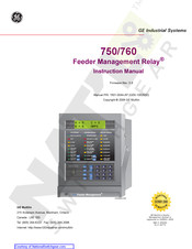
Feeder Management Relay 760
GE Feeder Management Relay 760 Manuals
Manuals and User Guides for GE Feeder Management Relay 760. We have
1
GE Feeder Management Relay 760 manual available for free PDF download: Instruction Manual
GE Feeder Management Relay 760 Instruction Manual (346 pages)
Brand:
GE
| Category:
Protection Device
| Size: 8.82 MB
Table of Contents
Table of Contents
3
1 Getting Started
9
Important Procedures
9
Cautions and Warnings
9
Manual Organization
9
Inspection Checklist
9
Using the Relay
10
Menu Navigation
10
Panel Keying Example
11
Changing Setpoints
11
Application Example
13
Commissioning
16
2 Introduction
17
Overview
17
Description
17
Theory of Operation
19
Ordering
21
Specifications
22
Applicability
22
Inputs
22
Measured Parameters
23
Protection Elements
23
Monitoring Elements
25
Control Elements
26
Outputs
27
Output Relays
27
Cpu
27
Physical
28
Testing
28
Approvals
28
Mechanical
29
Drawout Case
29
Installation
29
Unit Withdrawal and Insertion
31
Rear Terminal Layout
33
Electrical
35
Typical Wiring
35
Phase Sequence and Transformer Polarity
36
Current Inputs
36
Voltage Inputs
39
Control Power
40
Trip/Close Coil Supervision
40
Logic Inputs
42
Analog Input
42
Analog Outputs
43
RS485 and RS422 Communications
44
RS232 Communications
46
Irig-B
46
4 User Interfaces
47
Front Panel Interface
47
Description
47
LED Status Indicators
48
Keypad Operation
49
Messages
50
750/760Pc Software Interface
53
Description
53
Requirements
53
Hardware Configuration
53
Installation/Upgrade
54
Startup and Communications Configuration
56
Using 750/760PC
57
Advanced 750/760PC Features
61
5 Setpoints
65
Overview
65
Setpoints Message Map
65
Setpoint Entry Methods
68
Setpoint Access Security
68
Common Setpoints
68
Logic Diagrams
70
S1 Relay Setup
71
Passcode
71
Communications
71
Clock
74
Event Recorder
74
Trace Memory
75
Data Logger
76
Front Panel
77
Default Messages
78
User Text Messages
78
Clear Data
79
Installation
79
S2 System Setup
80
Current Sensing
80
Bus VT Sensing
80
Line VT Sensing
81
Power System
81
Flexcurves
82
S3 Logic Inputs
83
Overview
83
Logic Inputs Setup
83
Breaker Functions
85
Control Functions
86
User Inputs
86
Block Functions
87
Block Overcurrent Functions
88
Transfer Functions
89
Reclose Functions (760 Only)
90
Miscellaneous Functions
90
S4 Output Relays
91
Relay Operation
91
Trip Relay
92
Close Relay
93
Auxiliary Relays
94
Self-Test Warning Relay
95
S5 Protection
96
Overview
96
Phase Current
100
Neutral Current
106
Ground Current
111
Sensitive Ground Current
115
Negative Sequence
122
Voltage
127
Frequency
132
Breaker Failure
135
Reverse Power (if Enabled)
136
S6 Monitoring
137
Current Level
137
Power Factor
139
Fault Locator
140
Demand
142
Analog Input
147
Analog Outputs
150
Overfrequency
152
Equipment
153
Pulse Output
159
S7 Control
160
Setpoint Groups
160
Synchrocheck
163
Manual Close Blocking
165
Cold Load Pickup Blocking
167
Undervoltage Restoration
169
Underfrequency Restoration
170
Transfer
171
Autoreclose (760 Only)
182
S8 Testing
193
Output Relays
193
Pickup Test
194
Analog Outputs
194
Simulation
195
Factory Service
198
6 Actual Values
199
Overview
199
Actual Values Main Menu
199
A1 Status
203
Virtual Inputs
203
Hardware Inputs
203
Last Trip Data
204
Fault Locations
205
Clock
205
Autoreclose (760 Only)
205
A2 Metering
206
Metering Conventions
206
Current
207
Synchronizing Voltage
209
Power
209
Energy
210
Analog Input
212
A3 Maintenance
213
Trip Counters
213
Arcing Current
213
A4 Event Recorder
214
Event Records
214
A5 Product Info
217
Technical Support
217
Revision Codes
217
Calibration Dates
217
7 Communications
219
Overview
219
Protocols
219
Physical Layer
219
Modbus Protocol
220
Description
220
Data Link Layer
220
Algorithm
221
Message Timing
221
Modbus Operations
222
Modbus Function Codes
222
Exception Responses
225
Clock Synchronization of Multiple Relays
226
Reading the Event Recorder
227
Reading Trace Memory
228
Reading the Data Logger
229
Accessing Data Via the User Map
229
Memory Map Organization
230
Modbus Memory Map
231
Data Formats
258
Dnp Communications
267
Device Profile Document
267
DNP Implementation
269
DNP Point Lists
270
8 Commissioning Tests
277
Overview
277
Safety Precautions
277
Requirements
277
Conventions
278
Test Equipment
278
Installation Checks
278
Wiring Diagrams
279
Inputs/Outputs
280
Logic/Virtual Inputs 1 to 14
280
Virtual Inputs 15 to 20
284
Output Relays
285
Metering
286
Current Metering
286
Voltage Metering
286
Power Metering
288
Demand Metering
289
Analog Input Metering
291
Protection Schemes
292
Setpoint Groups
292
Phase Overcurrent
292
Neutral Overcurrent
296
Ground Overcurrent
299
Negative-Sequence Overcurrent and Voltage
300
Voltage
301
Frequency
305
Breaker Failure
307
Reverse Power
308
Monitoring
309
Current Monitoring
309
Fault Locator
309
Demand Monitoring
310
Analog Inputs
311
Overfrequency Monitoring
311
Power Factor
312
VT Failure
312
Trip Coil Monitor
313
Close Coil Monitor
313
Breaker Operation Failure
313
Arcing Current
314
Analog Output Channels
314
Irig-B
314
Pulse Output
314
Advertisement
Advertisement
Related Products
GE Feeder Management Relay 750
GE MOTOR MANAGEMENT RELAY 469
GE TRANSFORMER MANAGEMENT RELAY 745
GE ReliaGear LV MCC
GE Refrigerators
GE Hotpoint RE1440H
GE Responder 1000
GE Responder 2000
GE RES1072
GE RES1072DTBB
GE Categories
Refrigerator
Ranges
Microwave Oven
Air Conditioner
Dishwasher
More GE Manuals
Login
Sign In
OR
Sign in with Facebook
Sign in with Google
Upload manual
Upload from disk
Upload from URL