Sign In
Upload
Manuals
Brands
GE Manuals
Monitor
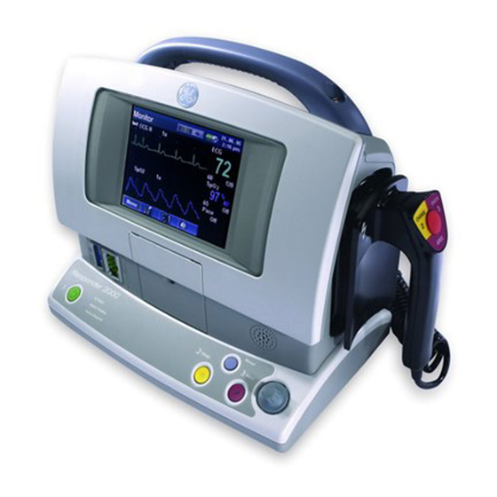
Responder 2000
GE Responder 2000 Manuals
Manuals and User Guides for GE Responder 2000. We have
2
GE Responder 2000 manuals available for free PDF download: Operator's Manual, Service Manual
GE Responder 2000 Service Manual (138 pages)
Defibrilator/monitor
Brand:
GE
| Category:
Medical Equipment
| Size: 10.1 MB
Table of Contents
Table of Contents
3
Section 1: Introduction
8
Overview
8
Description
9
Controls and Indicators
10
General Service Information
11
Navigation
11
Passwords
11
Battery Maintenance
11
Section 2: Maintenance
12
Overview
12
Equipment Setup
13
Required Tools
13
Procedure
13
Upgrade Software
14
Upgrade Printer Software
16
Update Serial and Model Numbers
17
Section 3: Troubleshooting
18
Overview
18
Safety Precautions
19
Who Should Perform Repairs
19
Service/Replacement Parts
19
Disposal
19
Repair Tools and Equipment
20
Troubleshooting Guide
20
General Troubleshooting
20
No Boot
21
If the AC Power LED Is Not Lit
21
If the AC Power LED Is Lit
21
Boot, but no Response
21
If the ECG Trace Is Not Moving
21
The Rotary Selection Knob Works Properly
21
The Rotary Selection Knob Does Not Work Properly
21
Bad Front Panel Leds
22
Buttons Do Not Work
22
The Rotary Selection Knob Does Not Work Properly
22
The Rotary Selection Knob Works Properly
22
Bad Speaker
23
Display Is DIM, Dark, Fuzzy, or Unreadable
23
If the Display Is DIM
23
If the Display Is Dark, Fuzzy, or Unreadable
23
Printing Problems
23
Battery Troubleshooting
24
Spo2 Not Working
24
Shock into Paddle Dock Fails
24
Shock into Patient Fails
25
No ECG from Paddles/Pads/Spoons
25
Service Required LED Is on
25
Section 4: Repair
26
Overview
26
Required Tools
27
Disassembly Overview
27
How to Replace Specific Components
28
Capacitors
28
Therapy Board
28
SPO2 Board
29
ECG Board
29
Display/Main Board/Printer
30
Main Board
30
Printer
30
Power Supply and Power Control Board
30
Switches and Fan
30
Assembly
31
Overview
31
Paddle Latch Assembly
31
Main Board and Printer Installation
32
Power Control Board and Power Supply Installation
36
ECG Board Installation
40
Display Installation
42
SPO 2 Board Installation
44
Therapy Board Installation
45
Capacitor Installation
46
Rear Cover Installation
47
Section 5: Performance Verification and Safety Testing
50
Overview
50
Required Equipment
51
Preventive Maintenance
51
Annual Inspection
51
Verify Operation
52
Checkout Procedures
52
Maintenance Menu Reference
53
Service Tests
54
Button Test
54
Printer Speed Test
55
Battery Readings
55
Display Test
56
ECG Lead Test
56
Temperature Readings
57
Fan Test
57
Device Configuration
58
Select Language
58
Stored Data Management
58
Clear Event Logs
58
Clear Service Required Indicator
58
Clear Settings Menu Password
58
Clear All Stored Data
58
Send Event Logs to PC
58
Send/Receive Stored Parameters
59
Visual Inspection
60
Operational Tests
60
Initial Power up
60
Maintenance Mode Tests
61
Verify Serial Communications
61
Required Equipment
61
Procedure
61
Defibrillator Tests
62
Energy Timeout Test
62
Defibrillator Test Chart
62
Paddles Test
63
Pads Test
63
Spoons Test
63
Pacing Test
64
ECG Tests
65
Required Equipment
65
ECG Connections Test
65
Lead Detection Test
66
ECG Lead Test
67
Paddles ECG Test
68
Thermal Printer Operation
68
Cardioversion Test
68
Spo 2 Operation
68
Safety Tests
69
Hipot Test
69
Required Equipment
69
ECG to Serial 4.0 KVAC Test
70
AC Line/Neutral to AC Ground 1.5 KVAC Test
70
1.5 KVAC Test
70
Apex Test Load to Apex and Sternum 3.0 KVDC Test
71
ECG to Apex and Sternum 3.0 KVDC Test
71
Apex and Sternum to Service Port 3.0 KVAC Test
71
Leakage Current Test
72
Required Equipment
72
Equipment Setup
72
Test Procedure
75
Alternate Safety Test Procedures
75
Test Equipment
75
Leakage Current "Measurement Device" (MD) Characteristics
76
Tests
76
Visual Inspection
76
Leakage Current
77
Patient Leakage Current to Ground
80
Patient Leakage Current, Mains on Applied Part (All Sip/Sops Grounded)
83
Insulation Resistance
85
Section 6: Parts and Accessories
86
Overview
86
Kits
87
Accessories
92
Power Cords
94
Section 7: Theory of Operation
95
Overview
95
System Overview
96
Functions
96
Features
96
System Interconnection Block Diagram
97
Component Descriptions
98
Main Board
98
Therapy Board
98
ECG Board
98
Power Control Board
98
Spo 2 Board
98
Section 8: Specifications and Safety
99
Overview
99
Specifications
100
Physical Dimensions
102
Environmental Requirements
102
Operating Conditions
102
Storage and Shipping Conditions
102
Rhythmx ® ECG Analysis Algorithm
103
Detection Rate
103
Fine VF
103
Asystole
103
Noise Detection
103
Non-Committed Shock
103
Sync Mode
104
SVT (Supraventricular Tachycardia) Discriminators
104
SVT Rate
104
Continuous Monitoring for Shockable Rhythm
104
Pacemaker Pulse Information
104
Star ® Biphasic Defibrillation Waveform
105
Energy Levels and Patient Impedance
106
Electromagnetic Compatibility Requirements
107
Emissions
107
Immunity
107
Environmental Standards
108
Shock and Vibration
108
Storage and Shipping
108
Electromagnetic Emissions Table
109
Electromagnetic Immunity Table
110
Rf Communications Table
113
Connectors
114
Case
114
Power Connector - IEC 320 Type - AC Power
114
Paddles/Pads Connector - GE Defibrillator Paddles
114
Paddle Connector ID Codes
115
ECG Connector - GE ECG Connector - Five Lead ECG
115
ECG Cable Identification Encoding
116
Spo Connector - GE Spo
117
Serial Service Connector - DB9-Female
117
Paddle Cradles (Test Load)
117
Main Cpu Pcba
118
J211 - Power Control Interface to Power Control PCBA
118
J214 - LCD Panel
119
J213 - LCD CCFL Backlight
120
J218 - UI Interface to Power Control PCBA
121
J216 - Speaker
123
J219 - Printer Head
123
J220 - Printer Motor
124
J221 - Spo
124
J210 - Therapy Pcba
125
J212 - Ecg Pcba
125
Therapy Pcba
126
J103 - Power Supply
126
J110 - Main CPU PCBA Interface
126
J109 - Paddles Control Connector
127
J101, J102, J108 - Paddles HV Connectors
127
J104, J105, J106, J107 - Energy Storage Capacitor Connectors
128
J126, J127 - Internal Test Load Resistor
128
Ecg Pcba
128
J412 - Interface to Main CPU PCBA
128
J423 - Patient ECG Connection
129
Power Control Pcba
129
J315 - Power Input from DC Power Supply
129
J325 - Smart Battery Connector - Data and Power
129
J303 - Therapy Power
130
J311 - Power Control Interface from Main CPU PCBA
130
J318 - UI Features - Interface to Main CPU PCBA
131
J317 - Rs-232 Serial Service Interface
132
J323 - Fan
133
J324 - ENCODER "Trim Knob
133
J2 - Spo
133
Host Interface
133
Spo 2 PATIENT INTERFACE
134
Power Supply Module
134
Tb1 - Power Input
134
Power Output
134
Battery
135
J325 - Smart Battery Connector - Data and Power
135
Contact Information/Customer Service
136
Advertisement
GE Responder 2000 Operator's Manual (142 pages)
Brand:
GE
| Category:
Monitor
| Size: 1.32 MB
Table of Contents
Table of Contents
3
Section 1: Introduction
9
Overview
9
Responder 2000 Description
10
Indications for Use/Intended Use
11
Contraindications for Use
11
Contraindications for Manual Defibrillation Therapy
11
Contraindications for Semi-Automatic Therapy
11
Contraindications for Noninvasive Pacing Therapy
11
Safety Terms and Conditions
12
Dangers
12
Warnings
12
Precautions
15
Notes
18
Symbol Descriptions
19
Safety and Performance Standards
21
Operator Training Requirements
22
Section 2: Getting Started
23
Overview
23
Unpacking and Inspecting
24
Setting up the Responder 2000
25
Rechargeable Battery Installation and Removal
25
To Install the Rechargeable Battery
25
To Remove the Battery
26
To Check the Battery
26
Using the Battery Charger
27
The Battery Calibration Cyle
28
Calibrating Battery While Inside the Responder 2000
28
Charging Battery While Inside the Responder 2000
28
Connecting Paddles or Pads
29
Storing the Paddles
29
Connecting the Ecg Leads
30
Connecting the Spo 2 Cable (Optional Feature)
30
Connecting the Spo2 Cable (Optional Feature)
30
Installing Paper into the Printer
31
Powering the Responder 2000
32
Responder 2000 Front and Back Controls and Indicators
33
Responder 2000 Side Controls and Indicators
33
Responder 2000 Side Controls and Indicators
34
Z-Bar™ Indicator
35
Z-Bar for Pads and Paddles
35
Z-Bar for Spoons
35
Buttons
36
Power Button
36
Power on
36
Power off
36
Charge Button
37
Shock Button
37
Manual Button
38
Rotary Selector Knob
39
Soft Keys
39
Status Leds
40
Paddle Controls
40
Rs-232 Data Transfer Connection
40
Graphics Display
41
Monitor Screen
41
Information Bar
41
Message Area
41
Channel 1
42
Channel 2
42
Information Areas
43
Ecg Information Box
43
Spo 2 Information (Optional)
43
Pacing Information (Optional)
43
On-Screen Indicators
44
Battery Indicator
44
Battery Warning Messages
44
Heart Rate
45
Section 3: Using the Responder 2000
47
Overview
47
Responder 2000 Preparation
48
Patient Preparation
48
Using Pads
48
Applying Pads
49
Special Pad Placement Situations
49
Anterior-Lateral Placement of Pads for Defibrillation/Sync Shock (most Commonly Used)
50
Anterior-Posterior Placment of Pads for Non-Invasive Pacing and Defibrillation/Sync Shock
51
Changing Pads
52
Pads off Notification
52
Pads Shorted Notification
52
Using Ecg Electrodes
53
Applying Ecg Monitoring Electrodes
53
Using External Paddles
55
Inserting the Spoon Electrode
58
Defibrillator Application Guidelines
59
Defibrillation Modes
60
Choosing a Defibrillation Mode
60
Manual Mode
61
To Use Manual Mode
61
No Sync/Sync Option
63
Auto Sequence
63
Semi-Auto Shock Mode
64
To Use Semi-Auto Shock Mode
64
Ecg Monitoring
66
Activating and Deactivating Filters
66
Monitoring Heart Rate
66
Monitoring Pacemaker Patients
67
Non-Invasive Pacing (Option)
68
To Use Pacing Mode
69
Guidelines for the Application of External Pacemakers
70
Demand Pacing
71
Fixed-Rate Pacing
73
Pulse Oximetry (Option)
74
Application Tips
75
Printing
76
To Print
76
Snapshot
77
To Take a Snapshot
77
History Menu
77
Event Log
77
Patient Trends
77
Responding to Alarms
78
High Priority Alarms
78
Medium Priority Alarms
78
Low Priority Alarms
78
Visual Alarm Displays
79
Audible Alarms
79
Adjusting Heart Rate Alarm Limits
80
Setting the Ecg Source and Gain
80
Section 4: Configuring the Responder 2000 Settings
81
Overview
81
Settings Menu
82
To View the Settings Menu
82
Defibrillation Settings
85
Default Shock Energy Settings
86
Fibrillation Analysis Thresholds
86
Pacing Settings
87
To Change Pacing Settings from Settings Menu
87
To Change Settings from Startup Menu
88
Pacing Default Parameters
88
Channel Settings
89
Channel 1
90
Channel 2
90
Filters
90
Alarms/Sound Settings
91
Audio Defaults
92
Patient Triggers
92
Date/Time Settings
93
User Settings Menu
95
Facility
96
Set Password
97
System Settings Menu
98
Display Settings
99
Power-Up Settings
103
Power-Up Mode Default
104
Restore Defaults
105
Default Settings
106
Section 5: Maintenance & Service
107
Overview
107
Recommended Maintenance and Care
108
Visual Inspection
109
Cleaning Responder 2000 and Accessories
110
Recommended Cleaning Products
110
Cleaning Instructions
110
Printer Cleaning Instructions
111
Paddle and Internal Paddle Cleaning Instructions
111
Internal Paddle Sterilization Instructions
111
Inserting the Spoon Electrode
111
External Counter Electrode for Internal Defibrillation
112
Caring for Rechargeable Batteries
112
Calibrating the Battery Fuel Gauge
112
Recycling the Batteries
112
Defibrillator Checklist
113
Authorized Repair Service
117
Section 6: Specifications & Safety
119
Overview
119
Specifications
120
Physical Dimensions
122
Environmental Requirements
122
Operating Conditions
122
Storage and Shipping Conditions
122
Rhythmx ECG ANALYSIS ALGORITHM
123
Detection Rate
123
Fine Vf
123
Asystole
123
Noise Detection
123
Non-Committed Shock
123
Sync Mode
124
SVT (Supraventricular Tachycardia) DISCRIMINATORS
124
Svt Rate
124
Continuous Monitoring for Shockable Rhythm
124
Pacemaker Pulse Information
124
Star ® Biphasic Defibrillation Waveform
125
Star® Biphasic Defibrillation Waveform
125
Energy Levels and Patient Impedance
126
Safety Standards and Compliance Requirements
127
Electromagnetic Compatibility Requirements
127
Emissions
127
Immunity
127
Environmental Standards
128
Shock and Vibration
128
Storage and Shipping
128
Electromagnetic Emissions Table
129
Electromagnetic Immunity Table
130
Rf Communications Table
132
En 60601-1-2 Compliance
133
Compliant Cables and Accessories
133
Section 7: Accessories
135
Overview
135
Responder 2000 Accessories
136
Section 8: Contact Information/Customer Service
139
Overview
139
Contact Information / Customer Service
140
Advertisement
Related Products
GE Responder AED
GE Responder 1000
GE RES1072
GE RES1072DTBB
GE RES1072DTWW
GE Refrigerators
GE Hotpoint RE1440H
GE Feeder Management Relay 750
GE Feeder Management Relay 760
GE TRANSFORMER MANAGEMENT RELAY 745
GE Categories
Refrigerator
Ranges
Microwave Oven
Air Conditioner
Dishwasher
More GE Manuals
Login
Sign In
OR
Sign in with Facebook
Sign in with Google
Upload manual
Upload from disk
Upload from URL