Sign In
Upload
Manuals
Brands
GE Manuals
Medical Equipment
Venue R2
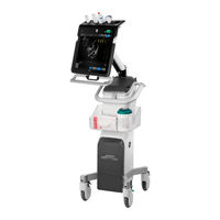
User Manuals: GE Venue R2 Portable Ultrasound
Manuals and User Guides for GE Venue R2 Portable Ultrasound. We have
1
GE Venue R2 Portable Ultrasound manual available for free PDF download: Service Manual
GE Venue R2 Service Manual (478 pages)
Brand:
GE
| Category:
Medical Equipment
| Size: 75.5 MB
Table of Contents
Table of Contents
3
Overview
26
Purpose of Chapter 1
26
Service Manual Overview
27
Contents in this Service Manual
27
Typical Users of the Basic Service Manual
27
Venue™ Models Covered in this Manual
28
Product Description
29
Important Conventions
31
Conventions Used in this Manual
31
Standard Hazard Icons
32
Safety Considerations
33
Introduction
33
Human Safety
33
Mechanical Safety
36
Electrical Safety
38
Venue™ Battery Safety
42
Patient Data Safety
42
Dangerous Procedure Warnings
43
Lockout/Tagout (LOTO) Requirements
44
Product Labels and Icons
45
Universal Product Labels
45
Label Descriptions
48
Venue™ External Labels Location
52
Returning/Shipping Probes and Repair Parts
53
EMC, EMI, and ESD
54
Electromagnetic Compatibility (EMC)
54
Compliance
54
Electrostatic Discharge (ESD) Prevention
55
General Caution
55
Direction 5771498-100, Revision
56
Contact Information
56
Customer Assistance
56
Overview
58
Purpose of Chapter 2
58
Console Requirements
59
Unit Environmental Requirements
59
Cooling Requirements
59
Lighting Requirements
59
Time and Manpower Requirements
59
Electrical Requirements
60
EMI Limitations
61
EMI Prevention/Abatement
62
Probe Environmental Requirements
62
Time and Manpower Requirements
63
Facility Needs
64
Purchaser Responsibilities
64
Required Facility Needs
65
Networking Pre-Installation Requirements
69
Connectivity Installation Worksheet
70
Overview
74
Purpose of Chapter 3
74
Setup Reminders
75
Average Setup Time
75
Setup Warnings
75
Safety Reminders
76
Receiving and Unpacking the Equipment
77
Warnings for Receiving and Unpacking the Equipment
77
Overview
77
Unpacking the Shipping Carton
80
Unpacking the Shipping Crate
85
Physical Inspection
90
EMI Protection
90
Preparing for Setup
91
Verifying Customer Order
91
Physical Inspection
91
Component Inspection
91
EMI Protection
94
Irection Revision Enue Ervice Anual
94
Completing the Setup
95
Purpose of this Section
95
System Specifications
95
Electrical Specifications
95
Connections on the I/O Rear Panel
96
Connecting Probes
97
Power On/Boot up
99
Power Shut down
99
Complete Power down
99
Configuration
100
Purpose of this Section
100
Venue™ Configuration
100
Service Screen Setup
114
Optional Peripherals/Peripheral Connection
115
Software Options Configuration
115
Connectivity Overview
116
Physical Connection
116
Stand-Alone Venue
116
Sneaker Net" Environment
116
Wireless Connection from Venue™ to DICOM Server
116
Connectivity Setup
117
Introduction
117
Select TCP/IP Screen
118
Setting up Non-Broadcasting (Hidden) Wireless Network Connection
119
Changing the AE Title And/Or Port Number (Port No.)
123
Wireless Network Configuration
124
Options Setup
125
Software Options
125
USB Flash Card Setup
125
Wireless Network Adapter
125
Insite Default Machine Contact Setup
126
Time Required
126
Preparations
126
Setup Procedure
126
Paperwork after Setup
130
Installation Acceptance Test Criteria
130
5771498-100, Revision
130
User's Manual(S)
130
Product Locator Installation Card
130
Overview
131
Purpose of Chapter 4
131
General Procedures
132
Overview
132
Power On/Boot-Up
133
Power Shutdown
136
Logging on to the Venue™ as "ADM
140
Data Management
140
Deleting Patient Information
141
Cockpit (Monitor) Position Adjustment
141
Moving and Transporting the Venue™ Ultrasound Scanner
141
Functional Checks
144
Overview
144
Performance Checks
144
2D Mode (B Mode) Checks
144
M Mode Checks
145
PW/CW Doppler Mode Checks
147
Probe/Connectors Check
150
Cineloop Check
151
Audio Check
152
Peripheral Checks
153
Mechanical Functions Checks
156
Electrical Tests
159
Overview
160
Purpose of Chapter 5
160
General Information
161
Introduction
161
Options
163
Connectivity
164
Purpose of this Section
164
Stand-Alone Venue
164
Direct Connection from Venue™ to a Review Workstation
164
Venue™ and a DICOM Server in a Network
164
5771498-100, Revision
165
Introduction
165
Insite Exc Icon
165
Initiating a Request for Service (RFS)
167
Insite Exc Definitions
169
Exiting Insite Exc
169
Insite Exc
165
Cockpit (Monitor) Module
170
General
170
Auxiliary Display (AD) Module
175
Speaker
175
External Input/Output
176
Front End Unit
177
General Information
177
Front End Interfaces
178
Signal Flow
178
Front End Power Supply (T-FEPS)
179
Front End (T-CFE) Board
179
Probe Selection Board (T-PSB)
180
Back End Processor
181
Introduction
181
Back End Processing (BEP) Module
181
BEP Block Diagram
183
Back End Interface (BIB) Board
184
Solid State Hard Drive
184
System Power Distribution
185
Introduction
185
AC Distribution
185
DC Power Distribution
185
System Power Management
186
Rechargeable Battery Pack
186
Cooling System
188
General Information
188
Peripherals
189
Internal Peripheral
189
External Peripherals
189
Common Service Desktop
190
Purpose of this Section
190
Irection Revision Enue Ervice Anual
190
Contents in this Section
190
Introduction
190
Ilinq Interactive Platform Features
190
Common Service Desktop (CSD)
191
Overview
193
Power Supply Adjustments
193
Cockpit (Monitor) Adjustments
193
Articulated Arm Movement Adjustments
194
Arm Movement Adjustment - General Instructions
194
Tilt Resistance Adjustments
194
Pan (Swivel) Resistance Adjustments
196
Arm Vertical Movement Adjustments
196
Arm Rotate Resistance Adjustments
197
Overview
198
Purpose of Chapter 7
198
Service Safety Considerations
199
Service Tools
200
Visual Guide
200
System Diagnostics
200
Gathering Troubleshooting Data
202
Purpose of this Section
202
Contents in this Section
202
Collect Vital System Information
202
Collect a 'Trouble Image' with Logs
202
Noise Troubleshooting
206
Purpose of this Section
206
Contents in this Section
206
Introduction
206
Overview of Types of Noise
206
Different Power Outlet
208
Different System
208
Different Location
208
Disconnect External Cables
208
Irection Revision Enue Ervice Anual
208
Audio Troubleshooting
209
Purpose of this Section
209
Audio Troubleshooting Procedure
209
Probes Not Recognized Troubleshooting
213
Purpose of this Section
213
Probes Not Recognized Procedure
213
System Does Not Turn on Troubleshooting
214
Purpose of this Section
214
BEP BIOS Jumper Setup
215
Cockpit ON/OFF Button Turns Orange -->BEP BIOS Jumper Setup
215
MPB to BIB Connection
216
BEP Fan Does Not Spin (ON/OFF Button Is Orange)-->MPB to BIB Connection
216
Front End Connections
217
Application Error: "Abnormal
217
No Auxiliary Display
218
System Stuck in Stand by Mode
219
System Stuck in Stand by Mode--> Verify T_CFE Board Revision
219
MPB Diagnostics Failure Troubleshooting
220
Purpose of this Section
220
MPB Diagnostics Procedure Troubleshooting
220
Overview
221
Purpose of Chapter 8
221
Visual Guide
221
Accessories - Replacement Procedures
222
Basic Storage Basket/Large Storage Basket Replacement Procedure
222
Power Cable Holder Replacement Procedure
223
Covers - Replacement Procedures
224
Overview of Covers
224
Lower Front Etower Cover Replacement Procedure
227
Left Side Etower Cover Replacement Procedure
228
Right Side Etower Cover Replacement Procedure
230
MID Thermal Baffle Cover Replacement Procedure
231
Upper Etower Front Cover Replacement Procedure
232
Printer Insert Cover Replacement Procedure
234
MPB Door Cover Replacement Procedure
236
RS Probe Cover Replacement Procedure
238
Riser Thermal Cover Replacement Procedure
239
Riser Cover Replacement Procedure
240
Irection Revision Enue Ervice Anual
240
System Modules- Replacement Procedures
244
Base Module Replacement Procedure
244
Front End Metal Door Replacement
247
Full Front End Replacement
251
SSD Module Replacement Procedure
254
Cockpit (Monitor) Replacement Procedure
256
PSU Module Replacement Procedure
260
Battery Module Replacement Procedure
263
Back End (BE) Module Replacement Procedure
265
BEP PCB Replacement Procedure
270
MPB Module Replacement Procedure
276
T-CFE (Cfront End) Module Replacement Procedure
280
T-PSB Module Replacement Procedure
284
Electronic Boards- Replacement Procedures
286
BIB Board Replacement Procedure
286
T-CFE Release Arm Replacement Procedure
289
Front End Power Supply (T-FEPS) Replacement Procedure
291
T-Trx Box Replacement Procedure
293
T-Trx Module Replacement Procedure
295
Mechanical Parts- Replacement Procedures
298
MPB Front Metal Door Replacement Procedure
298
MPB Guide L and Guide R Replacement Procedure
300
Halo Handle Replacement Procedure
303
Articulated Arm Replacement Procedure
306
Riser Replacement Procedure
311
Casters Replacement Procedure
315
Plastic Cable Guide for CFE Replacement Procedure
317
MPB Blower (Fan) Replacement Procedure
320
IPP Module Replacement Procedure
324
Cables - Replacement Procedures
328
MPB Rear USB Cable Replacement Procedure
328
MPB to Cockpit Cable Replacement Procedure
331
BE to Cockpit Cable Replacement Procedure
343
PSU to MPB DC Docking Cable Replacement Procedure
353
MPB to be PWR Cable Replacement Procedure
356
ON/OFF Switch Cable Replacement Procedure
359
Pcie Cable Replacement Procedure
362
MPB to BIB Control Cable Replacement Procedure
364
Printer USB Cable Replacement Procedure
367
Irection Revision Enue Ervice Anual
367
BEP Cables Replacement Procedure
369
MPB to T-FEPS - FRU Cable Replacement Procedure
377
MPB to Peripherals Harness - FRU Cable Replacement Procedure
380
Peripherals Replacement/Installation Procedures
384
Printer Replacement/Installation Procedure
384
Wi-Fi Adapter Replacement/Installation Procedure
390
ECG Installation Procedure for Systems with no Printer Installed
393
ECG Installation Procedure for Systems with Printer Installed
397
ECG Replacement Procedure
402
Operating System and Application Software Loading Procedures
404
Burning Disk-On-Key Media with SW Downloaded from GE Portal
404
Software Update Procedure
408
Software Upgrade Procedure from Venue™ R1 to Venue™ R2
413
Software Installation Procedure - General Overview
425
Software Installation Procedure
427
Software Recovery Procedure
432
Functional Checks to be Performed after Replacement Procedures
436
General Overview
436
Overview
440
Purpose of Chapter 9
440
List of Abbreviations
441
Main Assemblies and Sub Assemblies
442
Renewal Parts Lists and Diagrams
443
Mechanical Hardware Parts
443
Covers
446
System Power Distribution
448
Cockpit (Monitor) Parts
450
Etower
451
Probes
454
Software
454
System Power Cables
455
Accessories
456
Optional Peripherals
457
5771498-100, Revision
457
ECG Parts for Venue R2 Only
458
Overview
459
Care and Maintenance Inspections
459
Purpose of Chapter 10
459
Warnings
460
Why Do Maintenance
461
Keeping Records
461
Quality Assurance
461
Maintenance Task Schedule
461
Tools Required
463
Tools Required for Servicing the Venue
463
System Maintenance
464
Preliminary Checks
464
Functional Checks
465
Physical Inspection
467
Cleaning
468
Probe Maintenance
470
Probe Related Checks
470
Probe Handling
470
Basic Probe Care
471
Probe Cleaning
471
Returning and Shipping of Defective Probes
472
Electrical Safety Tests
473
Overview
473
Safety Test Overview
473
Outlet Test - Wiring Arrangement - USA and Canada
475
Grounding Continuity
476
Advertisement
Advertisement
Related Products
GE Revolution CT
GE Responder AED
GE Venue R1
GE Responder 1000
GE RTfino/RT3200
GE Precision RXi
GE Venue 40
GE Venue 50
GE Venue Go
GE Venue Fit
GE Categories
Refrigerator
Ranges
Microwave Oven
Air Conditioner
Dishwasher
More GE Manuals
Login
Sign In
OR
Sign in with Facebook
Sign in with Google
Upload manual
Upload from disk
Upload from URL