Sign In
Upload
Manuals
Brands
Honeywell Manuals
Controller
DCP301
Honeywell DCP301 Program Controller Manuals
Manuals and User Guides for Honeywell DCP301 Program Controller. We have
1
Honeywell DCP301 Program Controller manual available for free PDF download: User Manual
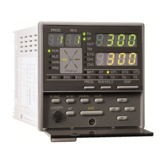
Honeywell DCP301 User Manual (187 pages)
Digital Program Controller
Brand:
Honeywell
| Category:
Controller
| Size: 1.27 MB
Table of Contents
Safety Precautions
3
Table of Contents
8
Conventions Used in this Manual
13
Chapter 1. GENERAL
14
Features
14
Basic Function Blocks
15
Data Structure
16
System Configuration
17
System Configuration by CPL Communications
17
Model Numbers
18
Model Selection Guide
18
Chapter 2. NAMES & FUNCTIONS of PARTS
19
Structure
19
Console
20
Basic Display State
20
Display
20
Keys
22
Functions Using Two or more Keys
25
Loader Jack
25
Input Type and Range no
26
Inputs
26
Chapter 3. MOUNTING
28
External Dimensions
28
Panel Cutout Dimensions
29
Mounting
30
Mounting Locations
30
Noise Generating Sources and Countermeasures
31
Dust-Proof Cover
31
Mounting Method
32
Chapter 4. WIRING
33
Wiring Precautions
33
Compensating Lead
35
Terminal Connections
36
Layout of Terminals and Recommended Lead Draw-Out Direction
37
Connecting the Ground and Power Supply
38
Power Supply
38
Ground
38
Wiring of Standard and Add-On Terminal Base
39
Standard Terminal Layout
39
Add-On Terminal Layout
39
Connecting Inputs (Analog Inputs)
40
Connecting Input 1
40
Connecting Control Outputs (Outputs 1, 2)
41
Relay Output (0D)
41
Current Output (5G)
41
Position-Proportional Output (2G)
41
Voltage Output (6D)
42
Heat/Cool Output (3D)
42
Heat/Cool Output (5K)
42
Connecting Auxiliary Outputs (Outputs 2, 3)
43
0D, 5G, 6D Auxiliary Outputs
43
2G, 3D, 5K Auxiliary Outputs
43
Connecting Event Output (Relay Output)
44
Connecting Time Event Output (Open-Collector)
45
4-12 Connecting External Switch (RSW) Input
46
4-13 Connecting for Communications
48
RS-485 Interface
48
4-14 Isolating Inputs and Outputs
51
Control Outputs 0D, 5G, 6D, 3D, 5K
51
Control Output 2G
51
Chapter 5. FUNCTIONS
52
Data
52
Data Types
52
Program Patterns
53
Patterns
53
Events 1 to 3
54
Time Events 1 to 5
57
PID Set Selection
59
G.soak (Guarantee Soak)
59
PV Start
60
Cycle
60
Pattern Link
61
Modes
62
Mode Type
62
Mode Types
62
Mode Transition
64
Mode Transition Operations
65
Mode Transition Limitations
66
Controller and Programmer
67
Input Processing Functions
68
Output Processing Functions
69
Control Output
69
SP Output
73
Auxiliary Output
73
Chapter 6. OPERATION
74
Turning the Power on
74
Switching the Basic Display
75
Display in Program Operation Mode
76
Display in Constant-Value Operation Mode
78
Program Selection
80
How to Select the Program no
80
External Switch (RSW) Operations
81
External Switch (RSW) Inputs
81
Program Selection
82
Read Timing
83
Manual Operation and Auto-Tuning
84
Manual Operation
84
Auto-Tuning (AT)
84
Chapter 7. PARAMETER SETUP
86
Parameter Setup
86
Selecting the Setting Group in the Parameter Setup
86
Moving Individual Items in the Parameter Setup
87
Changing Individual Items and How to Return from the Setup State
87
How to Use
89
Para
89
How to Register Functions to Keys
89
Parameter Setup List
92
Variable Parameter Settings "P a R a
92
Description of Variable Parameter Settings
95
Event Configuration Data Settings "E V
103
Description of Event Configuration Data
107
PID Parameter Settings "P I D
108
Setup Data Settings "S E T
112
Description of Setup Data Settings
118
Table Data Settings "T B L"
125
Description of Table Data Settings
126
Constant-Value Operation Data Settings "C N S T
127
Chapter 8. PROGRAM SETUP
128
Program Setup
128
How to Enter Program Setup
128
Selecting the Program No. to Set up
128
Mode Transition
129
Programming Map
131
Display Details
132
Setting up Pattern Items
132
Setting up Events 1 to 3 Items
133
Setting up Time Events 1 to 5
135
Setting up PID Set No. Items
136
Setting up G.soak (Guarantee Soak) Items
137
Setting up G.soak Time-Out Items
137
Setting up PV Start Items
138
Setting up Cycle Items
138
Setting up Pattern Link Items
139
Deleting Programs
139
Inserting and Deleting Segments
140
Copying Programs
141
Operation
141
General Reset
142
Operation
142
Chapter 9. TROUBLESHOOTING
143
Self-Diagnostics and Alarm Code Display
143
Self-Diagnostics at Power on
143
Self-Diagnostics at each Sampling Cycle
143
Intermittent Self-Diagnostics During Operation
143
Self-Diagnostics Only When Certain Functions Are Operating
144
Alarm Code Display
144
Alarm Categories
144
Trouble During Key Entry
145
The Program No. Does Not Change by Pressing
145
State
145
Display State
145
The Controller Does Not Change to RUN Mode by Pressing
145
Run/Hold
145
The Basic Display State
145
The Controller Does Not Change to HOLD Mode by Pressing
145
The Controller Cannot be Reset by Pressing
145
PROG + RUN/HOLD in the Basic
146
Display State
146
The Program Is Not Advanced by Pressing
146
Prog Disp
146
The Controller Does Not Change to FAST Mode by Pressing
146
In the Basic Display State
146
The Controller Does Not Change to MANUAL Mode by Pressing
146
The Controller Does Not Change to AUTO Mode by Pressing
146
The Basic Display State
146
Auto-Tuning (AT) Is Not Started by Pressing
146
In the Basic Display
147
State
148
Items Cannot be Changed by Pressing , in Program Setup
148
In Program Setup State
148
Program Deletion Cannot be Confirmed by Pressing
149
Func Clr
149
The Program Cannot be Copied by Pressing
149
General Reset Is Not Applied by Pressing
149
Func Clr Disp
149
Display State
149
Motor Adjustment Is Impossible
150
Normal Wiring for Direct Motor Rotation
151
Normal Wiring for Reverse Motor Rotation
151
Alarm Display Caused by Wrong Wiring and Causes
151
Replacing the Battery
152
BAT LED Blinking
152
Items to Prepare
152
Replacement Procedure
153
Chapter 10. SPECIFICATIONS
156
Specifications
156
Accessories/Option List
162
Soft Dust-Proof Cover Set
162
Hard Dust-Proof Cover Set
162
Terminal Cover Set
162
External Dimensions
163
Hard Dust-Proof Cover Set
164
Chapter 11. CALIBRATION
165
Precautions before Calibration
165
Equipment Needed
165
11-1 Quick Reference Table for Calibration Items
166
11-2 Calibration Procedures
170
Enter Calibration Mode
170
Function Test
171
PV Calibration
174
Cold Junction Sensor Calibration
176
Current Output Calibration
176
Revision History
184
Advertisement
Advertisement
Related Products
Honeywell DCP552 Mark II
Honeywell dcp100t
Honeywell DCP 250
Honeywell DC3300
Honeywell DC1000 SERIES
Honeywell DC33XB
Honeywell Design and Application
Honeywell D6 PRO
Honeywell DBC2000E1018
Honeywell DBC1500E1018-J
Honeywell Categories
Thermostat
Controller
Control Unit
Security Camera
Accessories
More Honeywell Manuals
Login
Sign In
OR
Sign in with Facebook
Sign in with Google
Upload manual
Upload from disk
Upload from URL