Sign In
Upload
Manuals
Brands
Honeywell Manuals
Temperature Controller
DHC Smile Series
Honeywell DHC Smile Series Manuals
Manuals and User Guides for Honeywell DHC Smile Series. We have
1
Honeywell DHC Smile Series manual available for free PDF download: Service Manual
Honeywell DHC Smile Series Service Manual (258 pages)
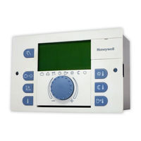
Smile SDC heating and district heating controller
Brand:
Honeywell
| Category:
Temperature Controller
| Size: 2.78 MB
Table of Contents
Table of Contents
3
1 Software Version
11
2 Safety Instructions
11
Intended Use
11
Requirements for Start-Up
11
Power Supply
12
Connection Conditions
12
Cable Cross-Sections
12
Maximum Cable Lengths
12
Cable Installation
12
Grounding and Zeroing
13
Hot-Water Temperature Greater than 60 °C
13
Connection of Accessory Parts
14
Maintenance and Cleaning
14
Safety Precautions for EMC-Compliant Installation
15
3 Overview
20
4 Abbreviations
21
5 Operation
22
Display and Operating Elements
22
Display (Basic Display)
23
Operating Elements
24
Input Button (Press / Turn)
24
Daytime Room Temperature" Button
24
Night-Time Room Temperature" Button
25
Daytime Hot-Water Temperature" Button
25
Operating Mode" Button (Basic Display)
26
Switching Time Programs / Holiday Programs" Button
33
System Information" Button
35
Manual Mode" / "Emission Measurement" Button
44
Access to the Technician / OEM Area
46
Heating Curve
47
Menu-Selection Level
48
Time - Date" Menu
54
Timeprograms" Menu
55
Selection of the Control Circuit
56
Selection of the Program
56
Selection of Day of the Week and Cycle
56
Programming Switching Times and Cycle Temperatures
57
System Parameters" Menu
72
Language Selection
72
Time Program
73
Operating Mode
74
Parameter Reset
76
Complete Reset
77
DHW" Menu
77
Night-Time Hot-Water Temperature
78
Legionella Protection Day
78
Direct Heating Circuit" / "Mixed Heating Circuit 1" / "Mixed Heating Circuit 2" Menu
78
Reduced Operation
79
Heating System
80
Error Messages
80
Parameter Settings
81
Hydraulics" Menu (HYDRAULIC)
81
System Parameters" Menu (SYSTEM)
85
Hot-Water Circuit" Menu (DHW)
89
Direct Heating Circuit" Menu (UNMIXED CIRC)
92
Mixed Heating Circuit 1 / 2" (MIX.VALVE - 1 / MIX.VALVE - 2) Menus
95
Heat Generator" Menu
99
District Hot Water" Menu (DIST.HEATING)
104
Return Increase" Menu (RETURN CONTR)
105
Solar" Menu (SOLAR)
106
Solid" Menu (SOLID FUEL)
107
Buffer" Menu (BUFFER)
108
Total Flow Regulation" Menu (MAIN SUPPLY)
109
Cascading" Menu (CASCADE)
110
Data Bus" Menu (BUS)
111
Relay Test" Menu (RELAY TEST )
111
Error Messages" Menu (ALARM)
112
Error Messages 2" Menu (ALARM 2)
113
Sensor Calibration" Menu (SENSOR ADJ.)
113
6 Control Functions
114
Variable Adjustment of the Hydraulic Parameters (Variable Inputs and Outputs)
114
Connection and Settings Table
116
Switching Time Program Enabling
117
Suppressing the Cycle Temperature on Time Program Level
118
Enabling "Separate Control Mode
118
Switching from SDC to DHC
119
Selection of Hydraulic Parameter Presettings
119
The Variable Inputs and Outputs of Device Series SDC/DHC 43
119
General Functions and Their Operation
120
Outside Temperature Sensing
120
Building Type
120
Heating Circuit Outside Temperature Assignment
121
Outside Temperature Emergency Operation Value
121
Outside Temperature Disable
122
Climate Zone
122
Design Temperature
122
Summer Switch-Off
123
System Frost Protection
124
Pump Forced Operation
127
7 Hydraulic Components
128
Heat Generator: Boiler
128
Heat Generator Start-Up Protection
128
Heat Generator Minimum Temperature Limit
129
Maximum Temperature Limit Heat Generator
130
Heating Circuits Minimum Temperature Limit
130
Heat Generator Sensor Control Mode
130
Minimum Burner Runtime
131
Switching: Multi-Stage Heat Generator/Switching Differential
131
Operation for Modulating Burners
136
Modulation of P Part (Xp)
137
Modulation of Sample Time Ta
137
Modulation of Integral Action Time Tn
138
Modulation of Runtime
138
Modulation of Start Time
138
Modulation of Start Power
139
Opentherm
140
Use of Boiler Sensor 2
141
External Heat Generator Cut-Off
141
Heat Generator Forced Discharge
141
Exhaust Gas Temperature Monitoring
142
Burner Counter Mode
143
Heat Generation, Heat Exchanger, District Heating
144
On/Off Operation of the District Heating Valve
145
Continuous Heat Exchanger Valve Control
145
District Heating Return Temperature Limit
147
Return Temperature Limit for Hot-Water Loading
149
Hot-Water Pre-Regulator with District Heating Systems
150
Mode of Operation: Hot-Water Pre-Control
151
Quick Hot-Water Control
152
Mode of Operation of Hot-Water Control Mode "External Operation
154
Conditional Parallel Operation for Mixed Heating Circuits
155
Circulation Pump Control Mode
155
Switch-Off of District Heating Control
156
Return Interval Flushing
156
Heat Meter for Additional Limitation According to the Volume Flow or Thermal Output
156
Charging Pump (CHP)
157
Primary Pump
158
Boiler Circuit Pump
158
Return Increase
159
Bypass Pump (RBP)
160
Return Maintenance through Controlled Feed Water Addition
160
Indirect Return Increase
161
Heating Circuit
161
General Heating Circuit Functions
161
Heating Curve
161
Heating Curve Setting (Heating Curve)
162
Reduced Operation
164
Heating System
164
Heating Circuit Temperature Limit
164
Heating Circuit Temperature Offset
165
Heating Circuit Pump Extended Running Time
165
Screed Function
165
Heating Circuit Constant Temperature Control
168
Fixed-Value Control
168
Consideration of the Room Temperature/Room Influence
169
Heating Circuit Room Connection
169
Heating Circuit Room Factor
170
Heating Circuit Room Controller
171
Switch-On/Switch-Off Optimisation
171
Room Setpoint Ramp
175
Heating Limit Function
175
Heating Circuit Room Frost Protection Limit
177
Mixed Heating Circuits Cooling Switch-Over
177
Heating Circuit Name
180
Room Thermostat Function (Maximum Room Temperature Limit)
181
Hot-Water Production
187
Hot-Water Tank Loading (SLP)
187
Circulation Pump (CIR.)
194
Solar/Solid Fuel/Buffer
196
Solar Function
196
Buffer Tank Function
199
Solid Fuel Function
212
Tank Loading Switch-Over
213
Hydraulic Buffer Relief (HBR)
215
Easy Enabling and Disabling of a Heating Pump
216
Other System Components
217
Global Fault Message Input
217
Global Fault Message Output
217
Timer
217
External Switching Modem
218
External Information
219
Demand Contact
219
Bus Communication
221
Bus Address of Central Device
221
Control Functions Via the Data Bus
222
Operation of Wall Devices
227
Cascading of Heat Generators in the Bus System
232
General Description of Cascading of Control Devices
232
Function of the Cascade Parameters
233
Mode of Operation of Cascade Control
234
Specifications
236
Commissioning, Maintenance and Troubleshooting Help
237
Automatic Set Function
237
Emission Measurement (Not for DHC 43)
238
Relay/Function Test
239
Error Messages
243
Basic Display/Fault Stack Fault Messages
248
Sensor Calibration
249
Full Controller Reset
249
Controller Time Correction
249
8 Technical Data
250
General
250
Installation Recommendations
251
Sensor Resistance Values
251
Ntc 20
251
Pt 1000
252
Sensor Measurement Ranges
252
Digital Inputs
253
9 Log
254
Index
255
Advertisement
Advertisement
Related Products
Honeywell DC1010
Honeywell DC1020
Honeywell DC1030
Honeywell DC1040
Honeywell DHC 43-1
Honeywell DHC 43-2
Honeywell DHC 43-3
Honeywell DHC
Honeywell DHC 43
Honeywell DHC 23
Honeywell Categories
Thermostat
Controller
Control Unit
Security Camera
Accessories
More Honeywell Manuals
Login
Sign In
OR
Sign in with Facebook
Sign in with Google
Upload manual
Upload from disk
Upload from URL