Sign In
Upload
Manuals
Brands
Honeywell Manuals
Measuring Instruments
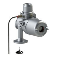
FlexLine SmartServo 954
Honeywell FlexLine SmartServo 954 Manuals
Manuals and User Guides for Honeywell FlexLine SmartServo 954. We have
2
Honeywell FlexLine SmartServo 954 manuals available for free PDF download: Service Manual, Installation Manual
Honeywell FlexLine SmartServo 954 Service Manual (305 pages)
Servo-based level gauge
Brand:
Honeywell
| Category:
Measuring Instruments
| Size: 9.53 MB
Table of Contents
Introduction
3
References
3
Table of Contents
5
1 General
9
Target Group for this Service Manual
9
Structure of this Manual
9
Trademarks
9
2 Safety and Security
10
Safety Conventions
10
Cautions
10
General
10
Warnings
10
Safety Instructions
11
Additional Information
11
Environmental Conditions
11
EC Declaration of Conformity (for EU)
11
Control Drawings for FM & CSA
11
Users
11
Liability
12
Labels
12
Personal Safety
13
Warnings and Cautions
13
General
13
Opening of the Instrument
13
Tools
13
Required Skills
14
Safe Area
14
Working Environment
14
Commissioning and Maintenance
14
Accordance to Regulations
15
Explosion Safety
15
Atex
15
Iecex
15
IC (Industry Canada)
16
Low-Voltage Directive
16
2.10 Security Considerations
17
Security Note 1
18
Security Note 2
18
Security Note 3
18
How to Report a Security Vulnerability
19
3 Principal of Servo Measurement
20
Level Measurement
21
Interface between Two Products
21
Relative Density
21
Servo Gauges
22
4 System Architecture
24
954 Smartservo Flexline Architecture
24
954 Smartservo Flexline System Architecture Overview
24
Flexconn Modules
25
A Typical Flexconn PCB Layout
26
Jumpers
27
2 Function Leds
28
Health LED
28
1 Temperature Sensor
29
3 Voltage Monitors
29
Locations of the 3 Voltage Monitors
29
Health Entity
30
Status Entities
30
Commissioned Entity
31
Function-Specific Entities
32
Generic Entity
32
HART Smartview Display
33
An Impression of the HART Smartview
33
General
33
Status Entities on HART Smartview
34
Generic Entities on HART Smartview
35
Specific Entities on HART Smartview
35
Engauge Service Tool
36
Example of an Engauge Screen
36
Board-Specific Entities in Engauge
37
Function-Generic Entities on Engauge
37
Generic Entities in Engauge
37
Status Entities in Engauge
37
5 Service Tools
38
HART Smartview Versions
38
Connections
38
General
38
HART Smartview Controls
39
HART Smartview Menu Structure
41
HART Smartview Screens
41
Start-Up Screen
42
Menu Screen
42
Display Contrast Screen
43
The Display Contrast Screen
43
Display Settings Screen
44
Display Test Screen
44
Identification Screen
44
Extra Information Screen
45
Identification Screen Examples
45
Primary Value Screen
46
Primary Value (PV) Items
47
The Password Screen
48
Commands Menu Screens
48
The Board List Screen
48
The Function List Screen
49
The Command List Screen
49
Commissioning Menu Screen
50
The Function List Screen (Commissioning)
51
The Entity List Screen
51
HART Address Screen
53
Communication Statistics
53
Character Level Errors
54
Message Level Errors
54
Communication Activity
54
Connecting the Engauge Service Tool
55
Wired Connections Situation
55
Connecting the Engauge Service Tool - Wired Connections
55
Using Engauge
56
6 Installation
57
Checks before Starting the Commissioning
58
Installation of Measuring Drum and Displacer
59
Tools
59
Tool Set for 954 Smartservo Flexline (Part No. A1854062)
60
Installation of Measuring Drum
61
Installing Drum
61
Installation of Displacer
62
Mounting Displacer
62
Unlocking (Locking) the Motor Block
63
Motor Block (Un)Locked
63
Configuring Flexconn Boards
64
Introduction
64
Text Conventions
65
Enraf Fieldbus (HCI-BPM)
66
The HCI-BPM Board with Its Isolation Transformer
66
Commissioning the HCI-BPM
67
Product Level Measurement (TII-SRV)
69
Board Specific
74
Product Level
76
Displacer Level
78
Functional Safety Level
80
Interface 2 Level
81
Density
82
Operational Commands
83
Special Commands
86
Density Configuration
90
Compensation
93
Maintenance
97
Servo Auto Test
101
Roof Immersion (RIC)
103
Miscellaneous
105
Relay Contacts (FII-DO)
106
The Relays and Leds on the FII-DO Board
106
Operation Mode
107
Relay Configuration
107
Jumper Settings
107
The Relays’ Hardware Jumpers
107
Relay Mode
108
Alarm Mode
109
PV Monitor
109
Monitor Mode
109
Status Behavior
110
Remote Control
111
Not in Use
112
Commands
112
Deactivate
112
Acknowledge
113
LED Association
113
Terminal Allocation
113
Commissioned Entities
114
Board Commissioned Entity
115
Fail-Safe Level Application
115
FCI-HRT, HART Master
116
The FCI-HRT Board
116
Software Description
117
Standard HIMS Density Measurement System Diagram
118
Floating-Roof or Free-Venting Tank HIMS Density Measurement System
118
Flexconn Function Allocation
119
Alternate System Diagram Multi-Drop Digital Mode
120
Software Specifications
122
Accepted HART Addresses
122
P1 Pressure
123
Accepted PV Unit for a P1 HART Device
123
P1 Pressure Displayed Unit Types
123
P3 Pressure
124
Accepted PV Unit for a P3 HART Device
124
P3 Pressure Displayed Unit Types
124
HIMS Density
125
HIMS Configuration Principle
126
Average Temperature & Water Level Measurement
127
The FII-VT Board with Its Planar Transformer
127
VITO Interface Types
128
Tank and Temperature Probe Data (1)
129
Product Temperature
131
Vapour Temperature
132
Commissioning Parameters for MRT or RTD
135
Resistance Temperature Detector (RTD) Elements Positions
135
Multiple Resistance Thermometer (MRT) Parameters
136
Element Type Definitions
138
Commissioning Parameters for the 765 VITO Water Probe
141
Water Level
142
Commissioning Check
143
Average Temperature Measurement (FII-RTD)
144
The FII-RTD Board
144
Some Important Settings
145
Some Important Features
146
Temperature Range Check Feature
146
Low Element Usage
147
Low Element Usage Settings Overview
147
Commissioning Parameters for MPT Temperature Calculations
149
Commissioning Parameters for MRT Temperature Calculations
150
Commissioning Parameters for All Types of Probes
151
Engauge * Vapour Temperature * Tab
153
Engauge * Ambient Temperature * Tab
155
HART Analog Outputs (HCI-HAO)
156
The HCI-HAO Board
156
Functional Description
157
The Analog and Digital Signals Within the HART Communication
157
HART Universal Ccommands
158
HART Common Practice Commands
158
Other HCI-HAO Features
159
Calibration of the HCI-HAO
160
Board Commissioning
162
Basic Configurable Entities Overview
162
Hardware Configuration
166
Jumper Allocation
166
LED Allocation
166
TRL/2 Fieldbus (HCI-TRL)
167
System Description
168
System Architecture - Rex Replaced with 954 Smartservo Flexline
168
Before You Begin Migration
169
Device Mapping
169
Before Mapping the Device
169
Saving Configuration in Database
171
To Save the Configuration Settings in the Database
171
Configuration of Gauge Using Smartlink and Engauge
173
Configuration of Smartlink with TRL/2 Card
173
Configuration of the Smartlink System
173
HCM - GPU Module
174
HCM-GPU Screen
174
HCM-GPU Board Specific
175
Baud Rate
175
Turn Around Delay
175
HCM-GPU Slave
176
GPU Interface Address
176
Flexconn Interface Address
177
Password
177
Parity
177
Modem Control Type
177
FCM-TRL/2 Module
178
FCM-TRL/2 Screen
178
FCM-TRL/2 Specific
179
FCM-TRL/2 Modbus Master
180
Configuration of Gauge TRL/2 through Engauge
182
Firmware Upgrade
185
Firmware Upgrade through Engauge
185
Firmware Upgrade of HCI-TRL/2 or FCM-TRL/2 through CAN-SD Card
187
Replacement Scenario
188
Replacing Rex Gauge
188
Possible Configuration Scenarios - Flexline 954 Gauge
191
Configuration Scenario 1
191
Configuration Scenario 2
192
Configuration Scenario 3
192
Configuration Scenario 4
193
Troubleshooting
194
Gauge Scan Issue
194
TII-XR Card Detection Issue
194
If the TII-XR Card Is Appeared in Scanning
194
HCI-TRL/2 Detection Issue
195
Firmware Upgrade of HCI-TRL2 Using CAN-SD Card
195
Smart Link Scan Issue
195
Integrated Display (TII-LCD)
196
Gauge Scan after Novram Reset
196
Commissioning of TII-LCD
198
Commissioning Screens of Engauge
201
LCD Display Screens
204
TII-LCD Start up Screen
204
Start up Screen
204
TII-LCD Initial Screen
204
TII-LCD Level and Temperature Display Screen
205
Level Screens with Different Unit Configured
206
Level Screen with Different Alarms
206
Level Screen with Limit Switch Status
207
Level Screen with Different Displacer Status
207
Level Screen with Different Operational Status
208
Level Screen with Different Level Type
211
Level Screen with Tenth Millimeter Selection as Disable
211
Level Value with Health Status
212
Level Value with Board W&M Intended
213
Level and Temperature Value Screen with Different Contrast Value
214
Level and Temperature Value Screen with Different Backlight Brightness
215
Level and Temperature Value with Decimal Separator
215
Level and Temperature Value with Zero Format
216
Level and Temperature Value with Different Display Format
216
LCD Text
217
Display Record
217
Temperature Value with Different Units
217
Temperature Value with Different Health Status
218
Ambient Light Sensor
219
Error Handling
220
Leds
220
SIL Overfill and Underfill Protection (FII-SIL)
221
Safety Function Status
222
Errors
222
Safety Shutdown Reason Codes
225
Other Errors
226
Uncertain Conditions
226
Novram Entity Bcc Error
226
Novram Read Back Error
226
Proof Testing
227
Commissioning
227
Entities
227
Contact 2
231
Analog Output
234
All Outputs
238
Configuring the Servo Gauge
239
Tank Related Level Entities
240
Alarm Settings
240
Standard Level Calibration
241
Level Calibration with a Tank Top Reference Stop
241
Level Calibration Using the Top of Ball Valve
242
Interface Measurement
243
Calculation of Set Point
243
Advanced Configuration
245
Set Point Compensations
245
Wire Weight
246
Unbalance
246
Level Compensations
247
Magnetic Coupling
247
Magnetic Coupling Temperature
247
Wire Temperature
247
Elongation Free Wire and Elongation Wire on Drum
248
Tank Shell
248
Hydrostatic Deformation
250
Calculation of Upper Reference Movement
250
Example of Tank Ring Measures
251
Example Steel Storage Tank with Diameter of 83.82 M
252
Example of Hydrostatic Deformation Figures
253
Example of Hydrostatic Deformation Correction
253
Protection and Detection Settings
253
8 Operation
255
Repeatability Test
255
Lock Test
255
Freeze and Block Commands
255
Unlock
256
Dip Mode
257
Interface Measurement
257
Servo Auto Test
258
Verify Level Calibration against a Tank Top Reference Stop
261
Verify Level Calibration on Top of Ball Valve
262
Preventive Maintenance
263
Balance Test
263
Check Bearings
263
Measure Displacer Weight
263
Check Bearings Command
264
The Bearing Status Can be Viewed by Engauge
264
Measure Displacer Weight
265
Balance Test
266
Example of a Smooth Servo Unbalance Diagram (16 Points)
267
Example of a Smooth Run-Down Diagram (Segment Size ~3 CM)
269
Run-Down Test
269
Example of a Smooth Run-Down Diagram (Segment Size ~26 CM)
270
Example of an Erroneous Run-Down Diagram
270
Repeatability Test (Refer to Section 8.1)
271
Instrument Covers
271
Drum Compartment
271
Left-Side Image
272
Right-Side Image
272
Removing the Measuring Drum
273
Replacing the Drum Bearings
274
Replacing the Drum Shaft Bearings
274
The Electronic Compartment
275
Detailed Description
275
Dismantling the Electronic Compartment
276
Cross Section of the Electronic and Terminal Compartment
276
Position of Mounting Bracket Screws
278
Calibrating Force Transducer
279
Set of Test Weights (#S1854061)
279
Synchronizing the Reference Encoder
283
10 954 Density Option
284
10.1 Introduction
284
Functional Description
284
Principle of Operation
285
Installation on the Tank
285
Calibration of the 954 Level Gauge
285
Commissioning
285
Setting of Density Items
286
Interface Profile Measurement
287
Tank Profile and Interface Profile Density Measurement
287
Settings for a Tank Profile Measurement (Command Tank Profile)
287
Settings for an Interface Profile Measurement (Command Interface Profile)
288
Corrections
289
Manual Input
289
Data Items, Commands and Error Codes
289
10.3 Operation
289
10.4 Maintenance and Trouble Shooting
290
Level Status Bytes
291
Density Status Byte
291
11 Trouble Shooting
292
11.1 Problems with Displacer Movement
292
11.2 Status Codes
292
Informational Status Codes
293
Warnings
294
Errors
295
12 Appendix A: Article and Part Numbers
298
13 Appendix B: Additional Information on Displacers
301
Standard Displacer
302
Density Displacer
302
14 Appendix C: ASCII Table
303
Advertisement
Honeywell FlexLine SmartServo 954 Installation Manual (45 pages)
Brand:
Honeywell
| Category:
Measuring Instruments
| Size: 1.5 MB
Table of Contents
Table of Contents
5
1 General
8
Using this Installation Guide
8
Related Documents
8
Trademarks
8
Contact
8
2 Safety and Security
9
General
9
Safety Conventions
9
Warnings
9
Cautions
9
Safety Instructions
10
EC Declaration of Conformity (for EU)
10
Control Drawings for FM & CSA
10
Users
10
Additional Information
10
Environmental Conditions
10
Liability
11
Labels
11
Personal Safety
12
Warnings and Cautions
12
General
12
General Precautions
14
Accordance to Regulations
15
Explosion Safety
15
3 Principal of Servo Measurement
17
Principle of Measurement
17
Level Measurement
18
Interface between Two Products
18
Relative Density
18
4 Mechanical Installation
19
Preparation for Transportation of the Gauge
19
Process Connection
19
Orientation of 954 Smartservo Flexline Gauge on Tank
20
Bolts
21
Mounting a Pressure Gauge Set
21
Grounding
22
5 Electrical Installation
23
General
23
Grounding
23
Safety
24
General Relative Density
24
Installing the Cable Glands and Stopping Plugs
25
Cable Glands
25
Unused Cable Inlets
25
Installing the Glands, Conduits and Stopping Plugs
26
Conduits
26
Unused Cable Inlets
26
Electrical Connections
27
Grounding
27
Connections
27
Finishing Installation
39
Assembling the Terminal Block and Board Compartment's Lids
39
External Fusing
40
Cable Glands / Conduit
40
Grounding
41
Appendix A
43
Appendix A (Continuation)
43
Advertisement
Related Products
Honeywell AirAlert 96d
Honeywell 90DM4
Honeywell VoyagerGS 9590 Series
Honeywell Voyager 9520
Honeywell Voyager 9540
Honeywell Dolphin 9500
Honeywell PEHA Compact 952 JRM
Honeywell COMBISAFE 9535
Honeywell Voyager 9520/40
Honeywell 900U02-0100
Honeywell Categories
Thermostat
Controller
Control Unit
Security Camera
Accessories
More Honeywell Manuals
Login
Sign In
OR
Sign in with Facebook
Sign in with Google
Upload manual
Upload from disk
Upload from URL