Sign In
Upload
Manuals
Brands
Kenwood Manuals
Car Receiver
TM-V71E
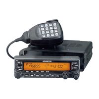
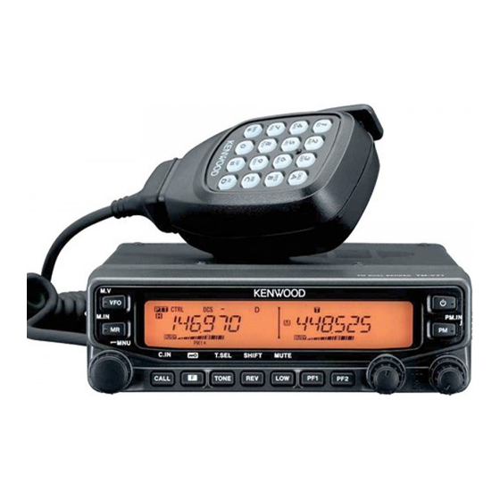
Kenwood TM-V71E Manuals
Manuals and User Guides for Kenwood TM-V71E. We have
3
Kenwood TM-V71E manuals available for free PDF download: Instruction Manual, Service Manual
Kenwood TM-V71E Instruction Manual (107 pages)
144/440 MHz FM Dual Bander 144/430 MHz FM Dual Bander
Brand:
Kenwood
| Category:
Car Receiver
| Size: 4.56 MB
Table of Contents
Instruction Manual
1
Table of Contents
5
Preparation
9
Supplied Accessories
9
Mobile Installation
9
Power Cable Connection
10
Antenna Connection
13
Front Panel Orientation
14
Accessory Connections
15
Getting Acquainted
16
Front Panel
16
Display
18
Rear Panel
20
Sub-Panel
20
Microphone (MC-59)
21
Basic Operations
22
Switching the Power On/ off
22
Adjusting the VOLUME
22
Adjusting the SQUELCH
23
Selecting a Band
23
Selecting Dual Band Mode/ Single Band Mode
24
Selecting a Frequency Band
25
Selecting an Operating Mode
26
Transmitting
27
Menu Mode
28
Menu Access
28
Menu Configuration
28
Character Entry
32
Operating through Repeaters
34
Repeater Access
34
TRANSMITTING a 1750 Hz TONE
38
Reverse Function
38
AUTOMATIC Simplex CHECKER (ASC)
38
Tone Frequency ID
39
Memory Channels
40
Simplex & REPEATER or ODD-SPLIT MEMORY CHANNEL
40
STORING Simplex and STANDARD REPEATER FREQUENCIES
41
Storing Odd-Split Repeater Frequencies
41
Recalling a Memory Channel
42
Clearing a Memory Channel
43
Naming a Memory Channel
43
Switching the Memory Name/ Frequency Display
44
Memory-To-Vfo Transfer
44
Channel Display Function
44
Programmable Memory (Pm)
46
APPLICATION Examples
47
Storing Data in Pm Channels
48
Recalling Pm Channels
48
Auto Pm Channel Store
49
Pm Channel Reset
49
Scan
50
Selecting a Scan Resume Method
51
Vfo Scan
51
Memory Scan
52
Group Scan
53
Program Scan
54
Mhz SCAN
56
Call Scan
56
Continuous Tone Coded Squelch System (Ctcss)
57
Using Ctcss
57
Ctcss Frequency ID
59
Digital Coded Squelch (Dcs)
60
Using Dcs
60
Dcs Code ID
62
Dual Tone Multi-Frequency (Dtmf)
63
Manual Dialing
63
Automatic Dialer
64
Dtmf Key Lock
66
Echolink
67
WHAT IS Echolink
67
STORING Echolink MEMORY
67
Selecting a Transmit Speed
68
SETTING up Echolink Sysop MODE
69
Auxiliary FUNCTIONS
70
Power-On Message
70
Display Brightness
70
Key Lock
71
Key Beep
72
Programmable Vfo
72
CHANGING the FREQUENCY STEP Size
73
Programmable Function Keys
74
Frequency Direct Entry
75
Automatic Power off (Apo)
75
S-Meter Squelch
76
Advanced Intercept Point (Aip)
76
Switching Fm/Am Mode
77
Beat Shift
77
Speaker Mute
77
Selecting an Output Power
78
Time-Out Timer (Tot)
78
External SPEAKER CONFIGURATION
79
Masking a Band
79
Display Partition Bar
80
Weather Alert (K Type Models Only)
81
Power on Password
82
Vgs-1 Optional Voice Guide & Storage Unit
83
Voice Announcements
83
Voice Recorder
86
Cross-Band/ Locked-Band Operation (K Type Models Only)
89
Repeater Hold
90
Repeater ID
90
Packet Operation
91
Data Band
91
Data Terminal Speed
91
Pc Port Speed
92
Sqc Output Setting
92
Wireless Operation (K Type Models Only)
93
Preparation
93
Control Operation
94
VFO/PART/PM/FULL Reset
95
Transceiver Reset
95
Options
97
Memory Control Program Mcp-2A
97
Connecting the Pg-5G/ Pg-5H Interface Cables
98
Installing the Dfk-3D Panel Kit
98
CONNECTING the PG-5F Extension CABLE
100
Installing the Vgs-1 Unit
101
Maintenance
102
General Information
102
Service
102
Service Note
102
Cleaning
102
Troubleshooting
103
Specifications
104
Advertisement
Kenwood TM-V71E Service Manual (104 pages)
144/430 (440) MHz FM DUAL BANDER
Brand:
Kenwood
| Category:
Two-Way Radio
| Size: 4.68 MB
Table of Contents
Table of Contents
1
Precautions for Disassembly
2
Disassembly for Repair
2
Frequency Configuration
3
Circuit Description
3
Receiver System
4
Band A/B VHF Receiver Circuit
4
Band A/B UHF Receiver Circuit
4
Transmitter System
5
Audio Circuit
5
Modulation Circuit
5
Transmitter Circuit
6
APC Circuit
6
Overheating Protection Circuit
7
Reference Oscillator Circuit
7
Power Supply Circuit
7
PLL Circuit
7
AF Signal System
8
Serial Control
8
Narrow/ Wide Switching Circuit
8
Beep Circuit and Mute Circuit
8
DATA Terminal Input/ Output Level
9
Transmission Signals
9
Microphone Key Input
9
Data Terminal and Peripheral Circuits
9
Panel Section
10
Reception Signals
10
Squelch Signal Output Circuit
10
Key, Encoder, Volume Input Circuit
10
Main MPU
11
Semiconductor Data
11
Shift Register
12
Panel MPU
13
Cross Point Switch
13
Electorical Volume IC
13
Components Descriptiont
14
Display Unit
14
Tx-Rx Unit
14
Terminal Function
19
Parts List
22
Exploded View
38
Packing
39
Front Panel
40
Measuring Equipment for Alignment
40
Preparation
40
Adjustment
40
Echolink Operation Check Method
41
How to Use the Data Terminal Short Plug
41
Rear Panel
41
Service Jig
41
Adjustment Items
42
Adjustment Mode
42
How to Enter the Adjustment Mode
42
LCD Display in the Adjustment Mode
42
Example of the Adjustment Mode Operation Procedure
43
Panel Key Operation in the Adjustment Mode
43
Adjustment Item, Adjustment Band Item, Display and the Frequency that Is Set to the Transceiver
44
Common Section
47
Transmitter Section
47
Reciever Section
52
Display Unit (X54-3590-00)
60
Display Unit, Component Side View
60
PC Board
60
Display Unit, Foil Side View
62
Tx-Rx Unit (X57-731X-XX)
64
TX-RX Unit, TX-RX Section, Component Side View
64
TX-RX Unit, TX-RX Section, Foil Side View
66
TX-RX Unit, Control Section, Component Side View
68
TX-RX Unit, Control Section, Foil Side View
70
Interconnection Diagram TX-RX Unit
72
Interconnection Diagram Display Unit
73
Schematic Diagram
74
Block Diagram
86
Receiver Section
88
Level Diagram
88
Cord Assembly
90
Optional Accessories
90
Specifications
91
Kenwood TM-V71E Service Manual (4 pages)
Brand:
Kenwood
| Category:
Transceiver
| Size: 0.2 MB
Advertisement
Advertisement
Related Products
Kenwood TM-D700A
Kenwood TS-2000
Kenwood TH-G71E
Kenwood TH-G71A
Kenwood TM-V708A
Kenwood TM-V71A
Kenwood TM-V708
Kenwood TM-V7A
Kenwood TM-V7E
Kenwood TM-V7A/E
Kenwood Categories
Car Receiver
Transceiver
CD Player
Amplifier
Receiver
More Kenwood Manuals
Login
Sign In
OR
Sign in with Facebook
Sign in with Google
Upload manual
Upload from disk
Upload from URL