Sign In
Upload
Manuals
Brands
Mitsubishi Electric Manuals
Amplifier
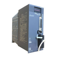
MELSERVO-JE MR-JE-300A
Mitsubishi Electric MELSERVO-JE MR-JE-300A Manuals
Manuals and User Guides for Mitsubishi Electric MELSERVO-JE MR-JE-300A. We have
1
Mitsubishi Electric MELSERVO-JE MR-JE-300A manual available for free PDF download: Instruction Manual
Mitsubishi Electric MELSERVO-JE MR-JE-300A Instruction Manual (310 pages)
SERVO AMPLIFIER MR-JE-_A Series
Brand:
Mitsubishi Electric
| Category:
Amplifier
| Size: 4.73 MB
Table of Contents
Safety Instructions
2
Table of Contents
8
Functions and Configuration
12
Summary
12
Function Block Diagram
13
Servo Amplifier Standard Specifications
15
Combinations of Servo Amplifiers and Servo Motors
16
Function List
16
Model Designation
18
Structure
19
Parts Identification
19
Configuration Including Peripheral Equipment
21
Installation
24
Installation Direction and Clearances
25
Keep out Foreign Materials
26
Encoder Cable Stress
27
Inspection Items
27
Parts Having Service Lives
28
Signals and Wiring
30
Input Power Supply Circuit
31
I/O Signal Connection Example
35
Position Control Mode
35
Speed Control Mode
40
Torque Control Mode
42
Explanation of Power Supply System
44
Signal Explanations
44
Power-On Sequence
45
Wiring CNP1 and CNP2
46
Connectors and Pin Assignment
48
Signal (Device) Explanations
50
Detailed Explanation of Signals
58
Position Control Mode
58
Speed Control Mode
63
Torque Control Mode
65
Position/Speed Control Switching Mode
68
Speed/Torque Control Switching Mode
70
Torque/Position Control Switching Mode
72
Forced Stop Deceleration Function
73
Base Circuit Shut-Off Delay Time Function
75
Vertical Axis Freefall Prevention Function
76
Residual Risks of the Forced Stop Function (EM2)
76
Alarm Occurrence Timing Chart
77
When You Use the Forced Stop Deceleration Function
77
When You Do Not Use the Forced Stop Deceleration Function
78
Interfaces
79
Internal Connection Diagram
79
Detailed Explanation of Interfaces
81
Source I/O Interfaces
85
Servo Motor with an Electromagnetic Brake
86
Safety Precautions
86
Timing Chart
87
Grounding
90
Startup
92
Switching Power on for the First Time
92
Startup Procedure
92
Wiring Check
93
Surrounding Environment
94
Startup in Position Control Mode
95
Power on and off Procedures
95
Stop
95
Test Operation
96
Parameter Setting
97
Actual Operation
97
Trouble at Start-Up
98
Startup in Speed Control Mode
100
Power on and off Procedures
100
Stop
100
Test Operation
101
Parameter Setting
102
Actual Operation
103
Trouble at Start-Up
103
Startup in Torque Control Mode
104
Power on and off Procedures
104
Stop
104
Test Operation
105
Parameter Setting
106
Actual Operation
106
Trouble at Start-Up
107
Display and Operation Sections
108
Display Flowchart
109
Status Display Mode
110
Diagnostic Mode
114
Alarm Mode
116
Parameter Mode
117
External I/O Signal Display
119
Output Signal (DO) Forced Output
122
Test Operation Mode
123
Parameters
128
Parameter List
128
Extension Setting 2 Parameters ([Pr. PE_ _ ])
133
Basic Setting Parameters ([Pr. PA
135
Gain/Filter Setting Parameters ([Pr. PB
144
Extension Setting Parameters ([Pr. PC
155
Extension Setting 2 Parameters ([Pr. PE
169
Extension Setting 3 Parameters ([Pr. PF
170
Normal Gain Adjustment
172
Different Adjustment Methods
172
Adjustment Using MR Configurator2
173
One-Touch Tuning
174
One-Touch Tuning Flowchart
174
Display Transition and Operation Procedure of One-Touch Tuning
176
Caution for One-Touch Tuning
184
Auto Tuning
185
Auto Tuning Mode
185
Auto Tuning Mode Basis
186
Adjustment Procedure by Auto Tuning
187
Response Level Setting in Auto Tuning Mode
188
Manual Mode
189
Gain Adjustment Mode
193
Special Adjustment Functions
196
Filter Setting
196
Machine Resonance Suppression Filter
196
Adaptive Filter II
199
Shaft Resonance Suppression Filter
201
Low-Pass Filter
202
Advanced Vibration Suppression Control II
202
Command Notch Filter
207
Gain Switching Function
208
Function Block Diagram
209
Parameter
210
Gain Switching Procedure
212
Tough Drive Function
215
Vibration Tough Drive Function
215
Instantaneous Power Failure Tough Drive Function
217
Troubleshooting
222
Alarm and Warning List
222
Remedies for Alarms
227
Remedies for Warnings
245
Dimensions
250
Servo Amplifier
250
Connector
253
Characteristics
256
Overload Protection Characteristics
256
Power Supply Capacity and Generated Loss
258
Dynamic Brake Characteristics
260
Permissible Load to Motor Inertia When the Dynamic Brake Is Used
261
Cable Bending Life
262
Inrush Current at Power-On
262
Options and Peripheral Equipment
264
Cable/Connector Sets
264
Combinations of Cable/Connector Sets
265
Regenerative Option
267
Combination and Regenerative Power
267
Selection of Regenerative Option
268
Selection of Regenerative Option
270
Dimensions
273
Junction Terminal Block MR-TB50
275
MR Configurator2
277
Selection Example of Wires
279
Molded-Case Circuit Breakers, Fuses, Magnetic Contactors (Recommended)
280
Power Factor Improving AC Reactor
280
Relay (Recommended)
281
Noise Reduction Techniques
282
Earth-Leakage Current Breaker
288
EMC Filter (Recommended)
290
Appendix
294
App. 1 Peripheral Equipment Manufacturer (for Reference)
294
App. 2 Compliance with Global Standards
294
App. 3 Analog Monitor
303
App. 4 Low-Voltage Directive
306
Advertisement
Advertisement
Related Products
Mitsubishi Electric MR-JE-_A
Mitsubishi Electric MELSERVO-JE MR-JE-70A
Mitsubishi Electric MELSERVO-JE MR-JE-10A
Mitsubishi Electric MELSERVO-JE MR-JE-100A
Mitsubishi Electric MR-JE-C
Mitsubishi Electric MR-JE-C Series
Mitsubishi Electric MR-J2S-100CL
Mitsubishi Electric Melservo MR-J3-40B1
Mitsubishi Electric MELSERVO MR-J2-60A
Mitsubishi Electric MR-J3-40T1
Mitsubishi Electric Categories
Air Conditioner
Controller
Projector
Inverter
Heat Pump
More Mitsubishi Electric Manuals
Login
Sign In
OR
Sign in with Facebook
Sign in with Google
Upload manual
Upload from disk
Upload from URL