Sign In
Upload
Manuals
Brands
Mitsubishi Electric Manuals
Amplifier
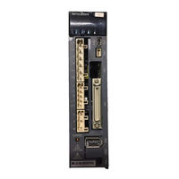
MR-J3-100T
Mitsubishi Electric MR-J3-100T Drives Manuals
Manuals and User Guides for Mitsubishi Electric MR-J3-100T Drives. We have
1
Mitsubishi Electric MR-J3-100T Drives manual available for free PDF download: Instruction Manual
Mitsubishi Electric MR-J3-100T Instruction Manual (802 pages)
Brand:
Mitsubishi Electric
| Category:
Amplifier
| Size: 10.95 MB
Table of Contents
Table of Contents
10
Functions and Configuration
20
Introduction
20
Features of CC-Link Communication Functions
20
Function Block Diagram
21
System Configuration
24
Servo Amplifier Standard Specifications
26
Function List
32
Model Code Definition
33
Combination with Servo Motor
34
Structure
36
Parts Identification
36
Removal and Reinstallation of the
42
Configuration Including Auxiliary Equipment
45
Selection of Operation Method
53
Installation
56
Installation Direction and Clearances
56
Keep out Foreign Materials
59
Cable Stress
59
Inspection Items
59
Parts Having Service Lives
60
CC-Link Communication Functions
62
Communication Specifications
62
System Configuration
63
Configuration Example
63
Wiring Method
64
Station Number Setting
66
Communication Baud Rate Setting
67
Occupied Station Count Setting
67
Functions
68
Function Block Diagram
68
Servo Amplifier Setting
69
I/O Signals (I/O Devices) Transferred To/From the Programmable Controller CPU
70
I/O Signals (I/O Devices)
70
Detailed Explanation of I/O Signals
73
Monitor Codes
83
Instruction Codes (Rwwn+2 Rwwn+3)
84
Respond Codes (Rwrn+2)
92
Setting the CN6 External Input Signals
93
Data Communication Timing Charts
95
Monitor Codes
95
Instruction Codes
97
Remote Register-Based Position/Speed Setting
99
Function-By-Function Programming Examples
102
System Configuration Example
102
Reading the Servo Amplifier Status
105
Writing the Operation Commands
106
Reading the Data
107
Writing the Data
110
Operation
113
Continuous Operation Program Example
116
System Configuration Example When 1 Station Is Occupied
116
Program Example When 1 Station Is Occupied
117
System Configuration Example When 2 Stations Are Occupied
119
Program Example When 2 Stations Are Occupied
120
Signals and Wiring
122
Input Power Supply Circuit
123
I/O Signal Connection Diagram
132
Explanation of Power Supply System
134
Signal Explanations
134
Power-On Sequence
135
CNP1, CNP2, CNP3 Wiring Method
137
Connectors and Signal Arrangements
146
Signal (Device) Explanation
147
I/O Devices
147
Input Signals
150
Output Signals
150
Power Supply
151
Detailed Description of Signals (Devices)
151
Forward Rotation Start Reverse Rotation Start Temporary Stop/Restart
151
Movement Completion Rough Match in Position
152
Torque Limit
154
Alarm Occurrence Timing Chart
155
Interface
156
Internal Connection Diagram
156
Detailed Description of Interfaces
157
Source I/O Interfaces
159
Treatment of Cable Shield External Conductor
160
Connection of Servo Amplifier and Servo Motor
161
Connection Instructions
161
Power Supply Cable Wiring Diagrams
162
Servo Motor with an Electromagnetic Brake
173
Safety Precautions
173
Timing Charts
174
Wiring Diagrams (HF-MP Series HF-KP Series Servo Motor)
176
Grounding
178
Operation
180
Switching Power on for the First Time
180
Startup Procedure
180
Wiring Check
181
Surrounding Environment
182
Startup
183
Power on and off Procedures
183
Stop
183
Test Operation
184
Parameter Setting
185
Point Table Setting
186
Actual Operation
186
Servo Amplifier Display
187
Automatic Operation Mode
189
What Is Automatic Operation Mode
189
Automatic Operation Using Point Table
191
Remote Register-Based Position/Speed Setting
201
Manual Operation Mode
207
JOG Operation
207
Manual Pulse Generator
208
Manual Home Position Return Mode
210
Outline of Home Position Return
210
Dog Type Home Position Return
211
Count Type Home Position Return
215
Data Setting Type Home Position Return
217
Stopper Type Home Position Return
218
Home Position Ignorance (Servo-On Position Defined as Home Position)
220
Dog Type Rear End Reference Home Position Return
221
Count Type Front End Reference Home Position Return
223
Dog Cradle Type Home Position Return
225
Dog Type First Z-Phase Reference Home Position Return
227
Dog Type Front End Reference Home Position Return Method
229
Dogless Z-Phase Reference Home Position Return Method
231
Home Position Return Automatic Return Function
233
Automatic Positioning Function to the Home Position
234
Roll Feed Display Function in Roll Feed Mode
235
Absolute Position Detection System
236
Outline of Absolute Position Detection Data Communication
237
Battery Replacement Procedure
238
Battery Installation Procedure
239
Procedure to Replace Battery with the Control Circuit Power off
239
Parameters
242
Basic Setting Parameters (No.pa )
242
Parameter List
242
Parameter Write Inhibit
243
Selection of Command Method and Maximum Torque of the HF-KP Series Servo Motor
244
Selection of Regenerative Option
245
Using Absolute Position Detection System
246
Follow-Up for Absolute Value Command System in Incremental System
246
Feeding Function Selection
247
Electronic Gear
247
Auto Tuning
250
In-Position Range
251
Torque Limit
252
Selection of Servo Motor Rotation Direction
252
Encoder Output Pulse
253
Gain/Filter Parameters (No.pb )
255
Parameter List
255
Detail List
256
Extension Setting Parameters (No.pc )
262
Parameter List
262
Detail List
264
S-Pattern Acceleration/Deceleration
270
Alarm History Clear
270
Rough Match Output
270
Software Limit
271
I/O Setting Parameters (No.pd )
272
Parameter List
272
Detail List
273
Stopping Method When Forward Rotation Stroke End (LSP) or Reverse Rotation Stroke End (LSN) Is off
282
Stopping Method When a Software Limit Is Detected
283
MR Configurator
284
Specifications
284
System Configuration
285
Station Selection
287
Parameters
288
Point Table
290
Device Assignment Method
292
Test Operation
296
Jog Operation
296
Positioning Operation
298
Motor-Less Operation
301
Output Signal (DO) Forced Output
302
Single-Step Feed
303
Alarm
306
Alarm Display
306
Batch Display of Data at Alarm Occurrence
307
Alarm History
309
Parameter Unit (Mr-Pru03)
310
External Appearance and Key Explanations
311
Specifications
312
Outline Dimension Drawings
312
Connection with Servo Amplifier
313
Single Axis
313
Multidrop Connection
314
Display
316
Outline of Screen Transition
316
MR-PRU03 Parameter Unit Setting
317
Monitor Mode (Status Display)
318
Alarm/Diagnostic Mode
320
Parameter Mode
322
Point Table Mode
323
Test Operation Mode
324
Error Message List
328
General Gain Adjustment
330
Different Adjustment Methods
330
Adjustment on a Single Servo Amplifier
330
Adjustment Using MR Configurator
331
Auto Tuning
332
Auto Tuning Mode
332
Auto Tuning Mode Basis
333
Adjustment Procedure by Auto Tuning
334
Response Level Setting in Auto Tuning Mode
335
Manual Mode 1 (Simple Manual Adjustment)
336
Interpolation Mode
340
Differences between MELSERVO-J2-Super and MELSERVO-J3 in Auto Tuning
341
Special Adjustment Functions
342
Function Block Diagram
342
Adaptive Filter
342
Machine Resonance Suppression Filter
345
Advanced Vibration Suppression Control
347
Low-Pass Filter
351
Gain Switching Function
351
Applications
351
Function Block Diagram
352
Parameters
353
Gain Switching Procedure
355
Troubleshooting
358
Troubleshooting at Start-Up
358
State at Error Occurrence
359
CC-Link Communication Error
359
When Alarm or Warning Has Occurred
360
Alarms and Warning List
360
Remedies for Alarms
361
Remedies for Warnings
374
Point Table Error
376
Trouble Which Does Not Trigger an Alarm/Warning
377
Outline Drawings
386
Servo Amplifier
386
Connector
395
Characteristics
398
Overload Protection Characteristics
398
Power Supply Equipment Capacity and Generated Loss
400
Dynamic Brake Characteristics
403
Dynamic Brake Operation
403
The Dynamic Brake at the Load Inertia Moment
407
Cable Flexing Life
408
Inrush Currents at Power-On of Main Circuit and Control Circuit
409
Options and Auxiliary Equipment
410
Cable/Connector Sets
410
Combinations of Cable/Connector Sets
411
Encoder Cable/Connector Sets
419
Motor Power Supply Cables
434
Motor Brake Cables
436
Regenerative Options
438
BU2-(H) Brake Unit
451
Selection
452
Brake Unit Parameter Setting
452
Connection Example
453
Outline Dimension Drawings
460
RC-(H) Power Regeneration Converter
462
Power Regeneration Common Converter
465
External Dynamic Brake
473
Battery MR-J3BAT
478
Heat Sink Outside Mounting Attachment (MR-J3ACN)
479
Selection Example of Wires
481
Molded-Case Circuit Breakers, Fuses, Magnetic Contactors
488
Power Factor Improving DC Reactor
489
Power Factor Improving Reactors
491
Relays (Recommended)
492
Noise Reduction Techniques
493
Earth-Leakage Current Breaker
501
EMC Filter (Recommended)
503
MR-HDP01 Manual Pulse Generator
508
Communication Function
510
Configuration
510
Communication Specifications
512
Communication Overview
512
Parameter Setting
513
Protocol
514
Transmission Data Configuration
514
Character Codes
515
Error Codes
516
Checksum
516
Time-Out Processing
516
Retry Processing
517
Initialization
517
Communication Procedure Example
518
Command and Data No. List
519
Detailed Explanations of Commands
526
Data Processing
526
Status Display
528
Parameters
529
External I/O Signal Statuses (DIO Diagnosis)
532
Device ON/OFF
537
Disable/Enable of I/O Devices (DIO)
538
Input Devices ON/OFF (Test Operation)
539
Test Operation Mode
540
Alarm History
546
Current Alarm
547
Point Table
548
Servo Amplifier Group Designation
554
Other Commands
555
Indexer Positioning Operation
556
Function
556
Overview
556
Servo Amplifier Standard Specifications (Functions Only)
556
Function List
557
I/O Signals (I/O Devices) Transferred To/From the Programmable Controller CPU
558
I/O Signals (I/O Devices)
558
Detailed Explanation of I/O Signals
560
Monitor Codes
569
Instruction Codes (Rwwn 2 Rwwn 3)
570
Respond Codes (Rwrn 2)
577
Signal
578
Signal (Device) Explanation
578
Detailed Description of Signals (Devices)
580
Switching Power on for the First Time
584
Startup Procedure
584
Wiring Check
585
Surrounding Environment
586
Startup
587
Power on and off Procedures
587
Stop
587
Test Operation
588
Parameter Setting
589
Point Table Setting
590
Actual Operation
590
Servo Amplifier Display
591
Automatic Operation Mode
593
What Is Automatic Operation Mode
593
Automatic Operation Mode 1 (Rotation Direction Specifying Indexer)
594
Automatic Operation Mode 2 (Shortest Rotating Indexer)
604
Manual Operation Mode
613
Indexer JOG Operation
613
JOG Operation
615
Home Position Return Mode
616
Outline of Home Position Return
616
Torque Limit Changing Dog Type Home Position Return
618
Torque Limit Changing Data Setting Type Home Position Return
620
Home Position Return Automatic Return Function
621
Absolute Position Detection System
622
Outline of Absolute Position Detection Data Communication
623
Battery Replacement Procedure
624
Battery Installation Procedure
625
Procedure to Replace Battery with the Control Circuit Power off
625
Parameters
627
Basic Setting Parameters (No.pa )
627
Gain/Filter Parameters (No.pb )
638
Extension Setting Parameters (No.pc )
645
I/O Setting Parameters (No.pd )
652
Troubleshooting
657
Troubleshooting at Start-Up
657
State at Error Occurrence
658
CC-Link Communication Error
658
When Alarm or Warning Has Occurred
659
Point Table Error
677
Trouble Which Does Not Trigger an Alarm/Warning
678
Speed Control Operation
686
Function
686
Overview
686
Servo Amplifier Standard Specifications (Functions Only)
686
Function List
687
I/O Signals (I/O Devices) Transferred To/From the Programmable Controller CPU
688
I/O Signals (I/O Devices)
688
Detailed Explanation of I/O Signals
691
Monitor Codes
698
Instruction Codes (Rwwn 2 Rwwn 3)
699
Respond Codes (Rwrn 2)
706
Signal
707
Signal (Device) Explanations
707
Detailed Description of Signals (Devices)
708
Switching Power on for the First Time
710
Startup Procedure
710
Wiring Check
711
Surrounding Environment
712
Startup
713
Power on and off Procedures
713
Stop
713
Test Operation
714
Parameter Setting
715
Point Table Setting
716
Actual Operation
716
Servo Amplifier Display
717
Speed Control Operation
718
Changing Speed by Devices of Speed Selection 1 (Ryna) to Speed Selection 3 (Rync)
719
Changing Speed by Remote Register (Only When 2 Stations Are Occupied)
719
Parameter
721
Basic Setting Parameters (No.pa )
722
Gain/Filter Parameters (No.pb )
728
Extension Setting Parameters (No.pc )
734
I/O Setting Parameters (No.pd )
739
Troubleshooting
745
Troubleshooting at Start-Up
745
State at Error Occurrence
746
CC-Link Communication Error
746
When an Alarm or Warning Has Occurred
747
Point Table Error
748
Problems Without an Alarm or Warning
749
Appendix
756
App. 1 Signal Layout Recording Paper
756
App. 2 Twin Type Connector: Outline Drawing for 721-2105/026-000(WAGO)
756
App. 3 MR-J3-200T-RT Servo Amplifier
757
App. 4 Selection Example of Servo Motor Power Cable
761
App. 5 Program Example with MELSEC-A Series Programmable Controllers
762
(Point Table Positioning Operation)
762
App. 7 Symbol for the New EU Battery Directive
782
App. 8 Compliance with the European EC Directives
783
App. 9 Compliance with Ul/Cul Standard
786
App. 10 Model Change of MR-J3-200T
792
Advertisement
Advertisement
Related Products
Mitsubishi Electric Melservo MR-J3-10B
Mitsubishi Electric Melservo MR-J3-100B
Mitsubishi Electric Melservo MR-J3-10B1
Mitsubishi Electric Melservo MR-J3-100B4
Mitsubishi Electric MELSERVO MR-J3-10A1
Mitsubishi Electric MR-J3-10T
Mitsubishi Electric MR-J3-10T1
Mitsubishi Electric Melservo MR-J3-11KB
Mitsubishi Electric Melservo MR-J3-11KB4
Mitsubishi Electric Melservo MR-J3-15KB4
Mitsubishi Electric Categories
Air Conditioner
Controller
Projector
Inverter
Heat Pump
More Mitsubishi Electric Manuals
Login
Sign In
OR
Sign in with Facebook
Sign in with Google
Upload manual
Upload from disk
Upload from URL