Sign In
Upload
Manuals
Brands
Mitsubishi Electric Manuals
Amplifier
MR-JE-_A
Mitsubishi Electric MR-JE-_A Manuals
Manuals and User Guides for Mitsubishi Electric MR-JE-_A. We have
2
Mitsubishi Electric MR-JE-_A manuals available for free PDF download: Instruction Manual
Mitsubishi Electric MR-JE-_A Instruction Manual (370 pages)
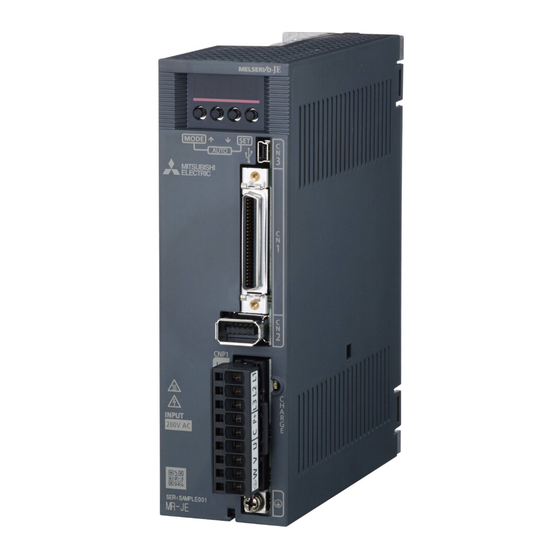
General-Purpose AC Servo Amplifier
Brand:
Mitsubishi Electric
| Category:
Amplifier
| Size: 3.59 MB
Table of Contents
Safety Instructions
2
Table of Contents
10
1 Functions and Configuration
16
Summary
16
Function Block Diagram
17
Servo Amplifier Standard Specifications
19
Combinations of Servo Amplifiers and Servo Motors
21
Function List
22
Model Designation
24
Structure
25
Parts Identification
25
Configuration Including Peripheral Equipment
27
2 Installation
30
Installation Direction and Clearances
31
Keep out Foreign Materials
32
Encoder Cable Stress
33
Inspection Items
33
Parts Having Service Life
34
Restrictions When Using this Product at Altitude Exceeding 1000 M and up to 2000 M above Sea Level
35
3 Signals and Wiring
36
Input Power Supply Circuit
37
I/O Signal Connection Example
42
Position Control Mode
42
Speed Control Mode
47
Torque Control Mode
49
Explanation of Power Supply System
51
Signal Explanations
51
Power-On Sequence
52
Wiring CNP1 and CNP2
53
Connectors and Pin Assignment
55
Signal (Device) Explanations
58
Detailed Explanation of Signals
67
Position Control Mode
67
Speed Control Mode
72
Torque Control Mode
74
Position/Speed Control Switching Mode
77
Speed/Torque Control Switching Mode
79
Torque/Position Control Switching Mode
81
Forced Stop Deceleration Function
82
Base Circuit Shut-Off Delay Time Function
84
Vertical Axis Freefall Prevention Function
85
Residual Risks of the Forced Stop Function (EM2)
85
Alarm Occurrence Timing Chart
86
When You Use the Forced Stop Deceleration Function
86
When You Do Not Use the Forced Stop Deceleration Function
87
Interfaces
88
Internal Connection Diagram
88
Detailed Explanation of Interfaces
90
Source I/O Interfaces
94
Servo Motor with an Electromagnetic Brake
96
Safety Precautions
96
Timing Chart
98
Grounding
101
4 Startup
102
Switching Power on for the First Time
103
Startup Procedure
103
Wiring Check
104
Surrounding Environment
105
Startup in Position Control Mode
106
Power on and off Procedures
106
Stop
106
Test Operation
107
Parameter Setting
108
Actual Operation
108
Trouble at Start-Up
109
Startup in Speed Control Mode
111
Power on and off Procedures
111
Stop
111
Test Operation
112
Parameter Setting
113
Actual Operation
114
Trouble at Start-Up
114
Startup in Torque Control Mode
115
Power on and off Procedures
115
Stop
115
Test Operation
116
Parameter Setting
117
Actual Operation
117
Trouble at Start-Up
118
Display and Operation Sections
119
Display Flowchart
120
Status Display Mode
121
Diagnostic Mode
125
Alarm Mode
127
Parameter Mode
128
External I/O Signal Display
130
Output Signal (DO) Forced Output
133
Test Operation Mode
134
5 Parameters
140
Parameter List
140
Basic Setting Parameters ([Pr. PA
148
Gain/Filter Setting Parameters ([Pr. PB
156
Extension Setting Parameters ([Pr. PC
168
I/O Setting Parameters ([Pr. PD_ _ ])
179
Extension Setting 2 Parameters ([Pr. PE
184
Extension Setting 3 Parameters ([Pr. PF_ _ ])
185
6 Normal Gain Adjustment
188
Different Adjustment Methods
188
Adjustment on a Single Servo Amplifier
188
Adjustment Using MR Configurator2
189
One-Touch Tuning
190
One-Touch Tuning Flowchart
192
Display Transition and Operation Procedure of One-Touch Tuning
195
Caution for One-Touch Tuning
210
Auto Tuning
211
Auto Tuning Mode
211
Auto Tuning Mode Basis
212
Adjustment Procedure by Auto Tuning
213
Response Level Setting in Auto Tuning Mode
214
Manual Mode
215
Gain Adjustment Mode
219
7 Special Adjustment Functions
222
Filter Setting
222
Machine Resonance Suppression Filter
222
Adaptive Filter II
225
Shaft Resonance Suppression Filter
228
Low-Pass Filter
229
Command Notch Filter
234
Gain Switching Function
235
Function Block Diagram
236
Parameter
237
Gain Switching Procedure
239
Tough Drive Function
243
Vibration Tough Drive Function
243
Instantaneous Power Failure Tough Drive Function
245
Model Adaptive Control Disabled
248
Lost Motion Compensation Function
249
8 Troubleshooting
252
Explanations of the Lists
252
Alarm List
253
Warning List
257
9 Dimensions
260
Servo Amplifier
260
Connector
263
10 Characteristics
266
Overload Protection Characteristics
266
Power Supply Capacity and Generated Loss
267
Dynamic Brake Characteristics
269
Dynamic Brake Operation
270
Permissible Load to Motor Inertia When the Dynamic Brake Is Used
271
Cable Bending Life
271
Inrush Current at Power-On
272
11 Options and Peripheral Equipment
274
Cable/Connector Sets
274
Combinations of Cable/Connector Sets
275
Regenerative Option
277
Combination and Regenerative Power
277
Selection of Regenerative Option
278
Connection of Regenerative Option
280
Dimensions
284
Junction Terminal Block MR-TB50
286
MR Configurator2
288
Specifications
288
System Requirements
289
Precautions for Using USB Communication Function
290
Selection Example of Wires
291
Molded-Case Circuit Breakers, Fuses, Magnetic Contactors
292
Power Factor Improving AC Reactor
293
Relay (Recommended)
294
Noise Reduction Techniques
295
Earth-Leakage Current Breaker
301
EMC Filter (Recommended)
303
12 Communication Function (Mitsubishi Electric General-Purpose Ac Servo Protocol)
306
Structure
306
Configuration Diagram
306
Precautions for Using RS422/USB Communication Function
307
Communication Specifications
308
Outline of Communication
308
Parameter Setting
308
Protocol
309
Transmission Data Configuration
309
Character Codes
310
Error Codes
311
Checksum
311
Time-Out Processing
311
Retry Processing
312
Initialization
312
Communication Procedure Example
313
Command and Data No. List
314
Reading Command
314
Writing Commands
318
Detailed Explanations of Commands
320
Data Processing
320
Status Display Mode
322
Parameter
323
External I/O Signal Status (DIO Diagnosis)
327
Input Device On/Off
330
Disabling/Enabling I/O Devices (DIO)
330
Input Devices On/Off (Test Operation)
331
Test Operation Mode
332
Output Signal Pin On/Off (Output Signal (DO) Forced Output)
335
Alarm History
336
Current Alarm
337
Software Version
338
Appendix
340
App. 1 Peripheral Equipment Manufacturer (for Reference)
340
App. 2 Compliance with Global Standards
340
App. 3 Analog Monitor
351
App. 4 Low-Voltage Directive
354
App. 5 Using HF-KN Series and HF-SN Series Servo Motors
355
App. 6 When Turning on or off the Input Power Supply with DC Power Supply
357
1-Phase 200 V AC Class Power Supply
358
Directive
360
Advertisement
Mitsubishi Electric MR-JE-_A Instruction Manual (114 pages)
Servo amplifier
Brand:
Mitsubishi Electric
| Category:
Amplifier
| Size: 0.8 MB
Table of Contents
Safety Instructions
2
Table of Contents
10
1 Functions and Configuration
14
Summary
14
Function List
15
Communication Specifications
15
System Configuration
16
Diagrammatic Sketch
16
Cable Connection Diagram
17
2 Parameter
18
Detailed List of Parameters
19
Restrictions on Using Modbus-RTU Communication
22
3 Modbus Protocol
24
Modbus-RTU Message Format
24
Broadcast Communication
24
Modbus-RTU Communication Message Frame
25
Function Codes
26
List of Function Codes
26
Read Holding Registers (Reading Data in Holding Registers: 03H)
27
Diagnostics (Function Diagnostics: 08H)
29
Preset Multiple Registers (Writing Data in Multiple Holding Registers: 10H)
31
Processing at Occurrence of an Error
33
4 Modbus Registers
34
List of Available Registers
34
Monitor (Address: 2B01H to 2B7Fh)
35
List of Registers
35
Directions for Use
36
Parameter Setting (Address: 2001H to 27Ffh)
37
List of Registers
37
Directions for Use
37
Point Table Setting (Address: 2801H to 281Fh)
38
List of Registers
38
Directions for Use
38
Writing Command to EEP-ROM (Address: 1010H)
38
Directions for Use
39
Alarm Information (Address: 1001H)
40
List of Registers
40
Directions for Use
40
Alarm Number (Address: 2A41H)
40
Alarm Occurrence Monitor (Address: 2B81H to 2Bffh)
41
List of Registers
41
Directions for Use
42
Alarm History (Address: 2A00H to 2A0Fh)
43
List of Registers
43
Directions for Use
43
Alarm History Clear (Address: 2A40H)
43
Parameter Error Count (Address: 2A44H)
44
List of Registers
44
Directions for Use
44
Parameter Error List (Address: 2A45H)
44
Point Table Error (Address: 2A43H)
45
List of Registers
45
Directions for Use
45
External Input Pin Status (Address: 2C10H)
46
List of Registers
46
Directions for Use
46
External Output Pin Status (Address: 2C11H)
47
List of Registers
47
Directions for Use
47
Input Device Status (Address: 2C12H)
47
Directions for Use
48
Output Device Status (Address: 2C13H)
49
List of Registers
49
Directions for Use
50
Servo Amplifier Model (Address: 1008H)
51
List of Registers
51
Directions for Use
51
Servo Amplifier Software Version (Address: 100Ah)
51
Broadcast Setting (Address: 2D98H)
52
List of Registers
52
Directions for Use
52
Servo Motor Rated Speed (Address: 2D28H)
52
Servo Motor Maximum Speed (Address: 2D29H)
52
SDO Abort Code (Address: 2A60H)
53
List of Registers
53
Directions for Use
53
Access Log 1 (Address: 2A64H)
53
Access Log 2 (Address: 2A65H)
54
List of Registers
54
Directions for Use
54
Communication Error Count (Address: 2A68H)
54
Supported Profile Information (Address: 1000H)
55
List of Registers
55
Directions for Use
55
Device Information (Address: 1018H)
55
5 Driving Motor
56
Device Control
57
Function Description
57
Related Registers
58
Details of Registers
58
Directions for Use
59
Control Mode
60
Function Description
60
Related Registers
60
Details of Registers
60
Directions for Use
62
Home Position Return Mode
62
Function Description
62
Related Registers
63
Details of Registers
63
Directions for Use
67
JOG Operation Mode
68
Function Description
68
Related Registers
68
Details of Registers
69
Directions for Use
72
Point Table Operation Mode
73
Function Description
73
Related Registers
73
Details of Registers
74
Directions for Use
77
Program Operation Mode
79
Function Description
79
Related Registers
79
Details of Registers
80
Directions for Use
82
Touch Probe (Address: 60B8H to 60Bbh)
83
Function Description
83
List of Registers
83
Details of Registers
84
Directions for Use
86
Function Common to the Modes
88
List of Registers
88
Control Input (2D01H to 2D09H)
88
Control Output (2D11H to 2D19H)
93
Simultaneous Start Bit Setting (2D9Ah)
98
Controller Force Stop (2D9Bh)
98
Override (2Db0H)
99
Forward Torque Limit Value (60E0H)
99
Reverse Torque Limit Value (60E1H)
99
Current Position (6064H)
99
Current Speed (606Ch)
99
Current Torque (6077H)
100
Cam Number Setting (2D80H)
100
Current Cam Number (2D82H)
100
Cam Axis One-Cycle Length Setting (2D84H)
100
Cam Stroke Length Setting (2D85H)
100
Request Store CAM (2D88H)
101
CAM Area (2D89H)
101
CAM Data in CAM Area (2D8Bh)
101
6 List of Modbus Registers
102
7 Application of Functions
106
Connection with GOT2000 Series
106
Access to Modbus Registers
106
Advertisement
Related Products
Mitsubishi Electric MELSERVO-JE MR-JE-70A
Mitsubishi Electric MELSERVO-JE MR-JE-10A
Mitsubishi Electric MELSERVO-JE MR-JE-100A
Mitsubishi Electric MELSERVO-JE MR-JE-300A
Mitsubishi Electric MR-JE-C
Mitsubishi Electric MR-JE-C Series
Mitsubishi Electric MR-J2M-P8B
Mitsubishi Electric MR-J2S-350CP-S084 3
Mitsubishi Electric MR-J4-A4-RJ Series
Mitsubishi Electric MR-JE-40BF
Mitsubishi Electric Categories
Air Conditioner
Controller
Projector
Inverter
Heat Pump
More Mitsubishi Electric Manuals
Login
Sign In
OR
Sign in with Facebook
Sign in with Google
Upload manual
Upload from disk
Upload from URL