Sign In
Upload
Manuals
Brands
Mitsubishi Electric Manuals
Controller
MR-JET- G
Mitsubishi Electric MR-JET- G Manuals
Manuals and User Guides for Mitsubishi Electric MR-JET- G. We have
1
Mitsubishi Electric MR-JET- G manual available for free PDF download: User Manual
Mitsubishi Electric MR-JET- G User Manual (140 pages)
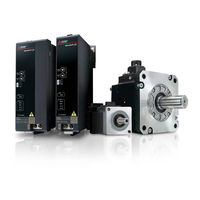
AC Servo System
Brand:
Mitsubishi Electric
| Category:
Controller
| Size: 19.46 MB
Table of Contents
Safety Instructions
3
About the Manual
5
U.s. Customary Units
5
Table of Contents
6
Chapter 1 Introduction
9
Wiring Procedure
9
Servo Amplifier/Motor Combinations
9
Rotary Servo Motor
9
Linear Servo Motor
10
Wiring Check
11
Power Supply System Wiring
11
I/O Signal Wiring
12
Surrounding Environment
13
Chapter 2 Installation
14
Mounting Direction and Clearances
15
Keeping out Foreign Materials
17
Cable Stress
17
Fan Unit Replacement Procedure
17
List of Applicable Fan Units
17
Fan Unit Removal Procedure
18
Fan Unit Installation Procedure
19
Restrictions When Using this Product at an Altitude Exceeding 1000 M and up to 2000 M
20
Chapter 3 Signals and Wiring
21
Example Power Circuit Connections
22
200 V Class
23
Example I/O Signal Connections
25
Explanation of Power Supply System
27
Explanation of Signals
27
Power-On Procedure
28
Wiring CNP1
29
Connectors and Pin Assignments
32
Precautions
32
Connectors and Pin Assignments
33
Signal (Device) Explanation
34
Input Device
34
Output Device
36
Power Supply
38
Interface
39
Internal Connection Diagram
39
Detailed Explanation of Interfaces
40
Source I/O Interface
41
Servo Motor with an Electromagnetic Brake
42
Connection Diagram
42
Grounding
43
Servo Amplifier
44
Mr-Jet-10G_/Mr-Jet-20G_/Mr-Jet-40G
44
Mr-Jet-70G_/Mr-Jet-100G
45
Mr-Jet-200G_/Mr-Jet-300G
46
Chapter 4 Dimensions
44
Connector
47
CN3 Connector
47
SCR Connector System (3M)
48
Chapter 5 Characteristics
49
Overload Protection Characteristics
49
Power Supply Capacity and Generated Loss
51
Power Supply Capacity
51
Generated Loss
52
Dynamic Brake Characteristics
53
Dynamic Brake Operation
54
Cable Flex Life
56
Inrush Current at Power-On
57
Chapter 6 Options and Peripheral Equipment
58
Cables/Connector Sets
58
Combinations of Cables/Connector Sets
59
Battery Branch Cable
61
Ethernet Cable
63
Regenerative Option
64
Combination and Regenerative Power
64
Selection of the Regenerative Option
65
Servo Parameter Setting
67
Connection of Regenerative Option
67
Mounting Direction
69
Dimensions
70
PS7DW-20V14B-F Junction Terminal Block (Recommended)
74
MR Configurator2
76
Engineering Tool
76
Precautions for Using USB Communication Function and Ethernet Communication Function
76
Battery
77
MR-BAT6V1SET-B Battery
77
MR-BAT6V1 Battery
84
Selection Example of Wires
85
Molded-Case Circuit Breakers, Fuses, Magnetic Contactors
86
Example Settings that Comply with IEC/EN/UL 61800-5-1 and CSA C22.2 No.274
87
Power Factor Improving AC Reactor
88
Relay (Recommended)
89
Noise Reduction Techniques
89
Earth-Leakage Current Breaker
97
Selection Method
97
Selection Example
98
EMC Filter (Recommended)
99
Chapter 7 Absolute Position Detection System
103
Outline
103
Characteristics
103
Restrictions
103
System Architecture
103
Servo Parameter Setting
104
Homing
104
Checking the Detected Absolute Position Data
104
Configuration and Specifications
105
Connecting the Battery Backup Type Absolute Position Encoder
105
Chapter 8 Using a Linear Servo Motor
106
Functions and Configuration
106
Outline
106
Configuration Including Peripheral Equipment
107
Startup
108
Startup Procedure
108
Setting
109
Magnetic Pole Detection
112
How to Replace Servo Amplifier Without Magnetic Pole Detection
119
Basic Functions
120
Homing
120
Linear Servo Control Error Detection Function
125
About MR Configurator2
127
Adjustment
128
Auto Tuning Function
128
Machine Analyzer Function
128
Characteristics
129
Overload Protection Characteristics
129
Power Supply Capacity and Generated Loss
130
Dynamic Brake Characteristics
131
Permissible Load to Motor Mass Ratio When the Dynamic Brake Is Used
132
Absolute Position Detection System
133
Chapter 9 Appendix
134
9.1 1-Phase 200 V AC Class Power Supply Input Using a Neutral Point of 3-Phase 400 V AC Class Power Supply
134
Revisions
136
Warranty
137
Trademarks
138
Advertisement
Advertisement
Related Products
Mitsubishi Electric Melservo-Jet MR-JET-10G
Mitsubishi Electric Melservo-Jet MR-JET-20G
Mitsubishi Electric Melservo-Jet MR-JET-40G
Mitsubishi Electric Melservo-Jet MR-JET-70G
Mitsubishi Electric Melservo-Jet MR-JET-100G
Mitsubishi Electric Melservo-Jet MR-JET-200G
Mitsubishi Electric Melservo-Jet MR-JET-300G
Mitsubishi Electric MR-JET
Mitsubishi Electric MELSERVO MR-JET-10G-N1
Mitsubishi Electric MR-JE-200BF
Mitsubishi Electric Categories
Air Conditioner
Controller
Projector
Inverter
Heat Pump
More Mitsubishi Electric Manuals
Login
Sign In
OR
Sign in with Facebook
Sign in with Google
Upload manual
Upload from disk
Upload from URL