Sign In
Upload
Manuals
Brands
Siemens Manuals
Relays
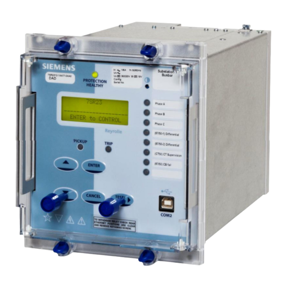
7SR23 DAD
User Manuals: Siemens 7SR23 DAD Impedance Protection
Manuals and User Guides for Siemens 7SR23 DAD Impedance Protection. We have
1
Siemens 7SR23 DAD Impedance Protection manual available for free PDF download: Manual
Siemens 7SR23 DAD Manual (226 pages)
High Impedance Protection Relay
Brand:
Siemens
| Category:
Relays
| Size: 3.41 MB
Table of Contents
Table of Contents
7
Section 1: Introduction
10
Current Transformer Circuits
10
External Resistors
10
Fibre Optic Communication
10
Front Cover
10
Table 1-1 7SR23 DAD Ordering Options
11
Figure 1-1 Connection Diagram: 7SR23 DAD Relay
12
Section 2: Hardware Description
13
General
13
Case
13
Front Cover
13
Table 2-1 Summary of 7SR23 DAD Relay Configurations
13
Power Supply Unit (PSU)
14
Operator Interface/ Fascia
14
Figure 2-1 7SR23 DAD with 3 + 8 Leds in E6 Case
14
Current Inputs
16
Binary Inputs
17
Figure 2-2 Binary Input Logic
17
Binary Outputs (Output Relays)
18
Virtual Input/Outputs
19
Self Monitoring
19
Protection Healthy/Defective
19
Figure 2-3 Binary Output Logic
19
Section 3: Protection Functions
20
Figure 3-1 Protection Functions
20
Overall High Impedance Differential Protection (87/50-N)
21
Figure 3-2 Logic Diagram: Differential Protection
21
Protection: Measured Earth Fault (50G)
22
Figure 3-3 Logic Diagram: Measured Earth Fault Element
22
Protection: Restricted Earth Fault (87REF)
23
Figure 3-4 Logic Diagram: Restricted Earth Fault Protection
23
Protection: Mode Selection
24
Pole Diff' + REF' Operation
24
Figure 3-5 Logic Diagram: '3 Pole Diff + REF' Protection
24
Pole Diff + EF' Operation
25
Figure 3-6 Logic Diagram: '3 Pole Diff + EF' Protection
25
REF1 + REF2' Operation
26
Figure 3-7 Logic Diagram: 'REF1 + REF2' Protection
26
Section 4: Control & Logic Functions
27
Zone Switching
27
Figure 4-1 Logic Diagram: Protection In/Out Switching
27
Quick Logic
28
Figure 4-2 Sequence Diagram Showing PU/DO Timers in Quick Logic (Counter Reset Mode Off)
29
Section 5: Supervision Functions
30
CT Supervision (CT50)
30
Figure 5-1 Logic Diagram: CT Supervision
30
Sustained Fault, CB Fail & CB Position Monitoring
31
Figure 5-2 Logic Diagram: 87/50SFM and 87/50BF
31
Cb/Circuit Position Monitoring
32
External CB Fail Input (Ext 87CBF)
32
Figure 5-3 Logic Diagram: CB Position Monitoring
32
Figure 5-4 Logic Diagram: Ext 87CBF
32
Trip Circuit Supervision (74TCS)
33
Figure 5-5 Logic Diagram: Trip Circuit Supervision Feature (74TCS)
33
Section 6: Other Features
34
Data Communications
34
IEC 61850 Communications
34
Maintenance
34
Output Matrix Test
34
Data Storage
35
General
35
Event Records
35
Waveform Records
35
Fault Records
35
Metering
36
Operating Mode
37
Control Mode
37
Table 6-1 Operating Mode
37
Real Time Clock
38
Time Synchronisation - Data Comms
38
Time Synchronisation - Binary Input
38
Time Synchronisation - IRIG-B (Optional)
38
Settings Groups
38
Password Feature
39
Section 1: Introduction
44
Relay Menus and Display
44
Operation Guide
45
User Interface Operation
45
Settings Display
47
Instruments Mode
48
Fault Data Mode
51
Section 2: Setting the Relay Using Reydisp Evolution
52
Physical Connection
52
Front USB Connection
52
Rear RS485 Connection (COM1)
53
Optional Rear Fibre Optic Connection (COM3 and COM4)
53
Optional Rear RS485 + IRIG-B Connection (COM3)
54
Optional Rear RS232 + IRIG-B Connection (COM3)
54
Optional Rear EN100 Ethernet Module (COM3)
55
Configuring Relay Data Communication
56
Connecting the Relay for Use with Reydisp
57
Section 1: Type Testing
62
General
62
Certification - CE Conformity
62
Reference
62
Inputs and Outputs
63
Auxiliary Power Supply
63
AC Current
64
Binary (Digital) Outputs
65
Binary (Digital) Inputs
65
Instrumentation and Data Comms
67
Instrumentation
67
Data Communication
67
Real Time Clock
68
Environmental Performance
69
Atmospheric Environment
69
Electrical Environment and Electromagnetic Compatibility
69
Mechanical Environment
71
Mechanical
72
Section 2: Protection Functions
73
Instantaneous Measured Earth Fault
73
Reference
73
Operate and Reset Level
73
Operate and Reset Time
73
87/50 High Impedance Differential Protection
74
Reference
74
Operate and Reset Level
74
Operate and Reset Time
74
Harmonic Rejection
74
87REF Restricted Earth Fault Protection
75
Reference
75
Operate and Reset Level
75
Operate and Reset Time
75
Harmonic Rejection
75
Section 3: Supervision Functions
76
CT50 CT Supervision Monitoring
76
Reference
76
Operate and Reset Level
76
Operate and Reset Time
76
74TCS Trip Circuit Supervision
77
Reference
77
Operate and Reset Time
77
Section 1: Introduction
82
Section 2: Physical Connection
83
Communication Ports
84
USB Interface (COM2)
84
RS485 Interface (COM1)
85
Optional Rear Fibre Optic Interfaces (COM3 and COM4)
86
Optional Rear RS485 (COM3)
90
Optional Rear RS232 (COM3)
90
Optional Rear EN100 Ethernet Module (COM3)
91
Section 3: IEC 60870-5-103 Definitions
92
Introduction
92
Section 4: Modbus Definitions
101
Introduction
101
Section 5: DNP3.0 Definitions
109
Device Profile
109
Implementation Table
112
Point List
117
Section 6: IEC61850 Protocol Support
130
Section 7: Modems
131
Connecting a Modem to the Relay(S)
131
Setting the Remote Modem
131
Connecting to the Remote Modem
131
Section 8: Glossary
132
Packaging
137
Unpacking, Storage and Handling
137
Recommended Mounting Position
137
Wiring
137
Earthing
137
Ancillary Equipment
138
Section 2: Equipment Operating Conditions
139
Current Transformer Circuits
139
External Resistors
139
Fibre Optic Communication
139
Front Cover
139
Disposal
139
Section 3: Dimensions and Panel Fixings
140
Relay Dimensions and Weight
140
Fixings
142
Crimps
142
Panel Fixings
142
Section 4: Rear Terminal Drawings
143
E6 Case
143
E8 Case
145
Section 5: Connection/Wiring/Diagrams
147
Wiring Diagram: 7SR230 Relay
147
Section 6: Data Comms Connections
148
RS485 Connection
148
IRIG-B Connections
148
Optional Fibre Optic Connections
148
Optional Additional RS485 Connections
150
Optional RS232 Connections
150
Additional (Optional) Ethernet Connection for IEC 61850
151
Section 7: Connection Diagrams
152
Typical AC Connections: 3 Pole Differential
152
Typical AC Connections: 3 Pole Differential + Earth Fault
153
Typical AC Connections: 3 Pole Differential + REF
154
Typical AC Connections: REF1 + REF2
155
Section 1: Common Functions
161
Overview
161
Before Testing
161
Safety
161
Sequence of Tests
161
Test Equipment
162
Precautions
162
Applying Settings
163
Tests
164
Inspection
164
Secondary Injection Tests
164
Primary Injection Tests
164
Putting into Service
164
AC Energising Quantities
165
Binary Inputs
166
Binary Outputs
167
Relay Case Shorting Contacts
167
Section 2: Protection Functions
168
Measured Earth Fault (50G)
169
Definite Time Overcurrent (50G)
169
Phase Differential Protection (87/50)
170
Restricted Earth Fault (87REF)
172
Section 3: Supervision Functions
174
Trip Circuit Supervision (74TCS)
174
CT Supervision (CT50)
175
Section 4: Control & Logic Functions
177
Quick Logic
177
Section 5: Testing and Maintenance
178
Periodic Tests
178
Maintenance
178
Troubleshooting
179
Section 6: Relay Software Upgrade Instructions
180
General
180
Replacing Firmware on a Product Installed on Site
180
Identify Which Software Is Currently Loaded
180
Overall Software Information
180
Product Configuration Information
180
Things to Do before Loading New Firmware/Software
181
Loading Firmware Using Front USB Port
181
Solving Software Upload Problems
181
Section 1: Introduction
188
Section 2: Protection Functions
189
High Impedance Differential Protection (87/50)
189
Basic Principles of Operation
189
Establishing the Required Stabilising Resistor Value
191
Limiting Circuit Over-Voltages (Metrosils)
191
Pole High Impedance Differential Protection
192
Restricted Earth Fault Protection (87REF)
193
Setting Calculations
194
Example 1 - 3-Pole Differential Busbar Protection
195
Example 2 - Restricted Earth Fault Protection
198
Section 3: CT Requirements for High Impedance Protection
201
CT Location Considerations
202
Cts Overlapping Circuit Breakers
202
Cts on 'Circuit' Side of the Circuit Breakers
203
Cts on 'Busbar' Side of the Circuit Breakers
204
Section 4: Control Functions
206
Zone Switching
206
Section 5: Supervision Functions
207
CT Supervision (CT50)
207
Trip Circuit Supervision (74TCS)
208
Trip Circuit Supervision Connections
208
Sustained Fault (87/50SFM)
210
Use of the 87/50-2 Element
211
CB Circuit Position
211
Section 6: Application Considerations and Examples
212
High Impedance Scheme Components
212
Busbar Protection
213
Primary Operate Current (Fault Setting)
213
CT Supervision Settings
213
Stability Level
213
Double Busbar Protection
213
Phase Differential Plus Earth Fault Configuration
215
Restricted Earth Fault Protection
216
Primary Operate Current (Fault Setting)
216
Stability Level
216
Protection of Auto-Transformer
217
Primary Operate Current (Fault Setting)
217
Stability Level
217
Protection of Motor, Generator or Reactor
218
Primary Operate Current (Fault Setting)
218
Stability Level
218
IEC61850 Applications
219
IEC61850 Implementation
219
Discrimination for 'Dual Zone' Faults
219
Section 7: Common Functions
221
Binary Inputs
221
Binary Outputs
223
Leds
223
Advertisement
Advertisement
Related Products
Siemens Argus 7SR21
Siemens Argus 7SR22
Siemens 7SR210 Argus
Siemens 7SR242 Duobias
Siemens 7SR220 Argus
Siemens Argus 7SR11
Siemens Argus 7SR12
Siemens 7SR45 Argus
Siemens 7SR18 Solkor
Siemens 7SR10 Argus Series
Siemens Categories
Industrial Equipment
Controller
Control Unit
Oven
Washer
More Siemens Manuals
Login
Sign In
OR
Sign in with Facebook
Sign in with Google
Upload manual
Upload from disk
Upload from URL