Sign In
Upload
Manuals
Brands
Siemens Manuals
Temperature Controller
RVL481
Siemens RVL481 Manuals
Manuals and User Guides for Siemens RVL481. We have
3
Siemens RVL481 manuals available for free PDF download: Installation Instructions Manual, Basic Documentation, Operating Instructions Manual
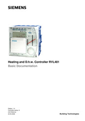
Siemens RVL481 Basic Documentation (118 pages)
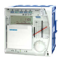
Heating and D.h.w. Controller
Brand:
Siemens
| Category:
Controller
| Size: 1.07 MB
Table of Contents
Table of Contents
3
1 Summary
11
Brief Description and Key Features
11
Equipment Combinations
11
Suitable Sensors
11
Suitable Room Units
12
Suitable Actuators
12
Communication
12
Passing on of Heat Demand Signal
12
Product Documentation
12
2 Use
13
Types of Plant
13
Types of Houses and Buildings
13
Types of Heating Systems
13
Functions
13
3 Fundamentals
15
Key Technical Features
15
Plant Types with Regard to Heating Circuit
15
Plant Types with Regard to D.h.w. Heating
15
Function Blocks
15
Plant Types
16
Selectable Combinations
16
Heating Circuit Plant Types
17
Plant Types
19
Setting Levels, Function Blocks and Plant Types
21
Heating Circuit Operating Modes
22
Automatic Operation
22
Continuously REDUCED Heating
22
Continuously NORMAL Heating
22
Protection Mode
22
Operating Mode
22
Manual Operation
23
Plant Type and Operating Mode
23
Operating State and Operational Level
24
4 Acquisition of Measured Values
25
Room Temperature (A6, B5)
25
Measurement
25
Handling Faults
25
Room Model
25
Flow and Boiler Temperature (B1)
25
Handling Faults
26
Outside Temperature (B9)
26
Measurement
26
Primary Return Temperature (B7)
26
Handling Faults
27
Secondary Return Temperature (B71)
27
Measurement
27
Flow Temperature (B3)
27
Storage Tank Temperature (B31, B32)
27
Handling Faults
28
Collector Temperature (B6)
28
Measurement
28
5 Function Block "Enduser Space Heating
29
Operating Lines
29
Setpoints
29
General
29
Frost Protection for the Building
29
Heating Program
29
Holiday Program
30
6 Function Block "Enduser D.h.w
31
Operating Lines
31
Setpoint
31
Actual Value
31
7 Function Block "Enduser General
32
Operating Lines
32
Switching Program 2
32
Time of Day and Date
32
Indication of Errors
33
8 Function Block "Plant Type
34
Operating Line
34
General
34
9 Function Block "Cascade Slave
35
Operating Lines
35
Mode of Operation
35
Boiler Sequence Release Integral (KFI)
35
Boiler Sequence Reset Integral (KRI)
35
10 Function Block "Space Heating
36
Operating Lines
36
ECO Function
36
Compensating Variables and Auxiliary Variables
36
Heating Limits
37
Mode of Operation
37
Operating Modes and Operating States
38
Room Temperature Source
38
Optimization
38
Definition and Purpose
38
Fundamentals
38
Process
39
Room Model Temperature
39
Optimum Stop Control
40
Quick Setback
40
Optimum Start Control
41
Boost Heating
41
Room Functions
42
Maximum Limitation of the Room Temperature
42
Room Influence
43
Heating Curve
43
Purpose
43
Basic Setting
43
Deflection
44
Parallel Displacement of Heating Curve
45
Display of Setpoints
45
Generation of Setpoint
46
Weather-Compensated Control
46
Demand-Compensated Control
46
11 Function Block "3-Position Actuator Heating Circuit
47
Operating Lines
47
Limitations
47
Flow Temperature Limitations
47
Setpoint Rise
48
3-Position Control
48
Excess Mixing Valve or Heat Exchanger Temperature
49
Pulse Lock
49
12 Function Block "Boiler
50
Operating Lines
50
Operating Mode
50
Limitations
50
Maximum Limitation of the Boiler Temperature
50
Minimum Limitation of the Boiler Temperature
51
Actions During D.h.w. Heating
51
2-Position Control
51
Control with a Single-Stage Burner
51
Control with a 2-Stage Burner
52
Frost Protection for the Boiler
53
Protective Boiler Startup
54
Protection against Boiler Overtemperatures
55
Operating Mode of Pump M1
55
13 Function Block "Setpoint of Return Temperature Limitation
56
Operating Line
56
Description
56
Minimum Limitation of the Return Temperature
56
Acquisition of Measured Values
56
Mode of Operation
56
Mode of Operation with a Single Device (with no Bus)
57
Mode of Operation in Interconnected Plants
57
14 Function Block "District Heat
58
Operating Lines
58
Limitations
58
Maximum Limitation of the Primary Return Temperature
58
Maximum Limitation of Return Temperature Differential (DRT Limitation)
59
Integral Action Time
60
Minimum Stroke Limitation (Suppression of Hydraulic Creep)
60
Flow Limitation
60
15 Function Block "Maximum Limitation of the Return Temperature, D.h
61
Operating Line
61
Purpose
61
Function
61
16 Function Block "Basic Settings D.h.w
62
Operating Lines
62
Assignment of D.h.w. Heating
62
Program for the Circulating Pump
62
General Mode of Operation
62
Operation of Circulating Pump During the Holiday Period
63
Frost Protection for D.h.w
64
Frost Protection in the D.h.w. Storage Tank
64
Frost Protection in the D.h.w. Storage Tank Flow
64
Frost Protection for the Secondary D.h.w. Flow
64
17 Function Block "Release of D.h.w. Heating
65
Operating Line
65
Release
65
Function
65
Release Programs
66
Heating During the Holiday Period
66
18 Function Block "D.h.w. Priority and Flow Temperature Setpoint
67
Operating Line
67
Settings
67
Priority
67
Absolute Priority
67
Shifting Priority
68
No Priority
68
Flow Temperature Setpoint
68
Flow Setpoint According to Maximum Selection
68
Flow Setpoint According to D.h.w
68
19 Function Block "D.h.w. Storage Tank
70
Operating Lines
70
Charging
70
Charging with Hot Water
70
Alternate D.h.w. Charging with Hot Water and Electricity
70
Temperature and D.h.w. Switching Differential
71
Boost of the D.h.w. Charging Temperature
72
Maximum D.h.w. Charging Time
72
Setpoint of Legionella Function
72
Forced Charging
73
Protection against Discharging
73
Purpose
73
Mode of Operation
73
Manual D.h.w. Charging
74
20 Function Block "3-Position Actuator for D.h.w
75
Operating Lines
75
Function
75
Flow Temperature Boost
75
Temperature Control
75
Pulse Lock
75
21 Function Block "Derivative Action Time D.h.w. Heating Via Heat Exchanger"
76
Operating Line
76
Description
76
22 Function Block "Multi-Functional Relay
77
Operating Lines
77
Functions
77
No Function
77
Outside Temperature Switch
77
ON / off According to the Time Switch
78
Relay Energized in the Event of Fault
78
Relay Energized During Occupancy Time
78
Relay Energized During Occupancy Time (Including Optimizations)
78
Relay Energized, if There Is Demand for Heat
78
Manually on / off
78
23 Function Block "Legionella Function
79
Operating Lines
79
Periodicity of Legionella Function
79
Time of Legionella Function
79
Dwelling Time at the Legionella Setpoint
79
Circulating Pump Operation During the Legionella Function
79
Mode of Operation
80
24 Function Block "Switching Program 3
81
Operating Lines
81
Function
81
25 Function Block "Service Functions and General Settings
82
Operating Lines
82
Display Functions
82
Flow Temperature Setpoint
82
Heating Curve
83
Hours Run Counter
83
Software Version
84
Identification Number of Room Unit
84
Commissioning Aids
84
Simulation of the Outside Temperature
84
Relay Test
84
Sensor Test
85
Test of H-Contacts
86
Auxiliary Functions
86
Frost Protection for the Plant
86
Flow Alarm
86
Manual Overriding of Operating Mode (Contact H1)
87
Pump Overrun
87
Pump Kick
88
Winter- / Summertime Changeover
88
Gain of Locking Signal
88
Entries for LPB
89
Source of Time of Day
89
Outside Temperature Source
90
Addressing the Devices
90
Bus Power Supply
91
Bus Loading Number
91
Heat Demand Output DC 0
91
26 Function Block "D.h.w. Solar Charging
92
Operating Lines
92
Functions
92
Temperature Differential ON/OFF Solar
92
Minimum Charging Temperature
93
Minimum Runtime
94
Collector Frost Protection Temperature
94
Collector Temperature to Protect against Overheating
95
Storage Tank Recooling
95
Evaporation Temperature of Heat Carrier
96
Maximum Limitation of Charging Temperature
97
Storage Tank Temperature Maximum Limitation
97
Collector Start Function Gradient
98
27 Function Block "Locking Functions
99
Operating Line
99
Locking the Settings on the Software Side
99
Locking the Settings for District Heat on the Hardware Side
99
28 Communication
100
Combination with Room Units
100
General
100
Combination with Room Unit QAW50
100
Combination with Room Unit QAW70
101
Combination with SYNERGYR Central Unit OZW30
103
Communication with Other Devices
103
29 Handling
104
Operation
104
General
104
Analog Operating Elements
105
Digital Operating Elements
105
Setting Levels and Access Rights
106
Commissioning
107
Installation Instructions
107
Operating Lines
107
Installation
107
Mounting Location
107
Mounting Choices
107
Electrical Installation
108
30 Engineering
109
Connection Terminals
109
Low-Voltage Side
109
Mains Voltage Side
109
Connection Diagrams
110
31 Mechanical Design
111
Basic Design
111
Dimensions
111
32 Technical Data
112
Advertisement
Siemens RVL481 Installation Instructions Manual (276 pages)
Brand:
Siemens
| Category:
Controller
| Size: 2.44 MB
Siemens RVL481 Operating Instructions Manual (32 pages)
Brand:
Siemens
| Category:
Temperature Controller
| Size: 0.24 MB
Table of Contents
Table of Contents
3
Info Button
5
Operating Modes
11
Room Temperature Is Not Correct
12
Changing the Heating Program
26
Tips
26
Faults and Manual Operation
27
Advertisement
Advertisement
Related Products
Siemens RVL470
Siemens RVL469
Siemens RVL482
Siemens RVL480
Siemens RVL479
SIEMENS RDD10 Series
Siemens RDF30U
Siemens REV-R.03/1
Siemens REV24
Siemens RCR10/868
Siemens Categories
Industrial Equipment
Controller
Control Unit
Oven
Washer
More Siemens Manuals
Login
Sign In
OR
Sign in with Facebook
Sign in with Google
Upload manual
Upload from disk
Upload from URL