Sign In
Upload
Manuals
Brands
Siemens Manuals
Controller
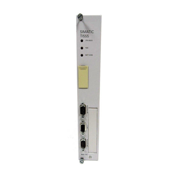
SIMATIC TI555
Siemens SIMATIC TI555 Manuals
Manuals and User Guides for Siemens SIMATIC TI555. We have
1
Siemens SIMATIC TI555 manual available for free PDF download: System Manual
Siemens SIMATIC TI555 System Manual (141 pages)
Brand:
Siemens
| Category:
Controller
| Size: 0.74 MB
Table of Contents
Table of Contents
5
Preface
13
Chapter 1 System Overview
16
Features
16
Table 1-1 TI545/TI555 Capacity/Performance
16
Figure 1-1 Typical TI555-1102 Control System
18
Hardware Description
20
Series 505 Base Assemblies
20
Local and Remote I/O
20
Communication Ports
21
I/O Port
21
Battery Backup
21
Real-Time Clock
22
Programming Software
22
Program Storage in EEPROM
22
Program Storage in EPROM
22
Table 1-2 Program Storage Using EEPROM and EPROM
22
Chapter 2 Pre-Installation Guidelines Planning Your Installation
23
Defining Control
23
Figure 2-1 Operator Safety Switch
23
Calculating Power Needs
24
Safety Considerations
25
Operator Safety Switches
26
Emergency Stop Switch
26
Figure 2-2 Emergency Stop Switch
26
JOG or INCH Switch
27
Figure 2-3 JOG or INCH Switch
27
Enclosure and Temperature Considerations
28
Enclosure Selection
28
Temperature Considerations
28
Guidelines for Fuses/Circuit Breakers
29
Fusing the Controller and Remote I/O Base
29
Figure 2-4 Fuse/Circuit Breaker Placement
29
Definition and Source of Electrical Noise
30
Electrical Noise
30
Correcting Noise Problems
31
Noise Snubbing
31
Figure 2-5 Load Noise Snubbing
31
Figure 2-6 Contact Noise Snubbing
32
Noise Isolation
33
Figure 2-7 Grounding Shielded, Twisted Pair Cables
33
Wiring Considerations
34
Guidelines
34
Power System Grounding
35
Earth Ground
35
Figure 2-8 Isolating Ground and Neutral from Conduit
35
Grounding the Controller
36
Grounding the Cabinet or Rack
36
Ground Connections
36
Figure 2-9 Grounding the TI545/TI555 Controller
36
Figure 2-10 Example of Ground Connection
37
Chapter 3 Installing Series 505 System Hardware
39
Overview of Installation Procedures
39
Series 505 Bases
40
Description
40
Table 3-1 Base Assembly Models
40
Rack Mounting Series 505 Base
41
PPX:505-6516, 16-Slot Base
41
Figure 3-1 Mounting Base to Standard 19-Inch Rack
41
Panel Mounting Series 505 Bases
42
Series 505 Bases PPX:505-6516, PPX:505-6508, PPX:505-6504
42
Figure 3-2 Screw-Hole Dimensions for PPX:505-6516/6511 Bases
42
Figure 3-3 Screw-Hole Dimensions for PPX:505-6504 Bases
43
Figure 3-4 Screw-Hole Dimensions for PPX:505-6508 Bases
44
Figure 3-5 Mounting Brackets to Base
45
Figure 3-6 Mounting Base in NEMA Enclosure
45
Installing Series 505 Power Supply
46
Power Budget for Series 505 Base
46
Power Supply Placement in Bases
46
Installing and Removing the Power Supply
46
Figure 3-7 Series 505 Module Placement in Base
46
Figure 3-8 Selecting Input Voltage-PPX:505-6660 Only
47
Installing the TI545/TI555 CPU
48
CPU/RBC Location in a Base
48
Figure 3-9 Location of CPU/RBC in a Series 505 Base
48
Installing and Removing the CPU
49
Figure 3-10 Installing CPU Module in a Series 505 Base
49
CPU Battery
50
Setting CPU Dipswitches
50
Figure 3-11 CPU Dipswitch Location
50
Using Port 1
51
Using Port 2
51
Figure 3-12 TI545/TI555 CPU Port Locations
51
Setting Baud Rates
52
Enabling Battery Backup
52
Table 3-2 Port 1 Baud Rate Settings
52
Table 3-3 Port 2 Baud Rate Settings
52
Installing Series 505 Remote Base Controller
53
RBC Placement in Bases
53
Dipswitches
53
Setting RS-232 Port Baud Rates (SW 2)
53
Figure 3-13 RBC Dipswitch Location
53
Table 3-4 RBC SW 2 (RS-232 Port) Baud Rate Settings
53
Series 505 RBC SW 3 (Factory) Dipswitch Settings
54
Output State Selection
54
Table 3-5 Series 505 RBC SW 3 (Factory) Dipswitch Setting
54
Figure 3-14 Series 505 RBC Jumper Locations
55
Installing and Removing Series 505 RBC
56
Assigning RBC Base Numbers
56
Series 505 RBC LED Display
57
Figure 3-15 Series 505 Remote Base Controller
57
Table 3-6 Series 505 RBC LED Messages
57
Installing Series 505 I/O Modules
58
Mixing I/O Modules
58
Installing and Removing I/O Modules
58
Figure 3-16 Installing and Removing Modules in a Series 505 Base
58
Chapter 4 Cabling and Wiring the System
60
Connecting Input Power
60
Guidelines
60
Wiring Power Supply
60
Figure 4-1 Supplying Power with the PPX:505-6660A
61
Cable Routing
62
Guidelines
62
Cable Routing Methods
62
Under-Floor Routing
63
In-Ceiling Routing
63
Surface Duct Routing
63
Mounting the Tap or Terminal Block
63
Installing Remote I/O Cables
64
Cabling Options
64
Trunk and Drop Lines
64
Figure 4-2 Trunk and Drop Line Example
64
User-Supplied Equipment
65
Mounting the Terminal Block
65
Programmable Controller and RBC Drop Lines
65
Preparing Cables (for Drop Lines)
66
Figure 4-3 9-Pin I/O Female D-Connector Pinout
66
Connecting a CPU Drop Line
67
Figure 4-4 Connecting to Terminal Block
67
Figure 4-5 Adding a Terminating Resistor
68
Table 4-1 Terminating Resistors
68
Connecting the RBC Drop Line
69
Figure 4-6 Attaching RBC to Terminal Block
69
Connecting Terminal Block Trunk Lines
70
Table 4-2 Maximum Cable Length for Trunk Lines
70
Alternate Cables
71
Table 4-3 Cable Characteristics
71
Configuration Requirements
72
Figure 4-7 Maximum Trunk Length
72
Figure 4-8 T Configuration
72
Figure 4-9 Multiple Tap Connections in Close Proximity
73
Figure 4-10 Spacing between Taps
73
Preparing Trunk Line Cables
74
Connecting Trunk Line to Terminal Blocks
75
Figure 4-11 Connecting Terminal Blocks
75
Connecting Modems
76
Overview
76
Figure 4-12 Modem Configuration
76
Dedicated Line Operation
77
Dial-Up Phone Line Operation
77
Connecting a Printer
78
Overview
78
Chapter 5 Using an EEPROM or EPROM
80
Introduction
80
Program Storage
80
Using an EEPROM
80
Table 5-1 Program Storage Using EEPROM and EPROM
80
Table 5-2 EEPROM/EPROM Portability between Controllers
80
Using an EPROM
81
EEPROM Functions
82
TI545/TI555 Memory and Mode Status at Power-Up
83
Table 5-3 TI545/TI555 Mode and Memory Status after Power-Up
83
Installing Eeproms and Eproms
84
Copying a Program into an EEPROM
86
Editing a Program Stored in EEPROM
88
Chapter 6 Starting up the TI545/TI555 System
90
Powering up the TI545/TI555 System
90
Overview
90
Start-Up Procedures
90
TI545 CPU Memory Configuration
92
Memory Configuration
92
Maximum Configurable Memory
92
Table 6-1 TI545-1102 CPU Memory Configuration
92
TI555 CPU Memory Configuration
93
Memory Configuration
93
Maximum Configurable Memory
93
Table 6-2 TI555-1101/1102 CPU Memory Configuration
93
Chapter 7 Troubleshooting
95
Troubleshooting by Using Auxiliary Functions
95
Overview
95
Power-Up Restart, Partial Restart, and Complete Restart
95
Table 7-1 Effects of Using AUX Functions 10, 11, and 12
96
Compare PLC to Disk
97
Run PLC Diagnostics
97
Display Failed I/O
97
Show PLC Diagnostic Cell
97
Troubleshooting by Reading Leds
99
Table 7-2 CPU Indicators
99
Troubleshooting Controller Fatal Errors
100
CPU Fatal Error Indications
100
Causes of CPU Fatal Errors
100
Controller Responses to Fatal Errors
100
Steps to Clear Fatal Errors
101
Calling for Assistance
101
Troubleshooting Controller Non-Fatal Errors
102
Troubleshooting by Using Status Words
103
Troubleshooting Eeproms or Eproms
104
Troubleshooting the Power Supply
105
Checking RS-485 (Twisted Pair) Cable Installation
107
Using Digital or Analog Meter
107
Table 7-3 Cable Resistance
107
Resistance below Minimum
108
Resistance above Maximum
108
Recommended Spare Parts List
109
Appendix A System Specifications
110
Series 505 System Specifications
110
Table A-1 Environmental Specifications
111
Table A-2 General Series 505 Specifications
112
Table A-3 Power Supply Electrical Specifications
113
Appendix B Module Power Consumption
114
Table B-1 Series 505 Module Power Requirements
115
Series 505 Modules
117
Appendix C TI545/TI555 CPU and I/O Compatibility
119
I/O Module Compatibility
119
I/O Modules Not Compatible with TI545/TI555 Cpus
119
Determining the Compatibility of a Module
120
Series 505 High Speed Counter
120
Reading the Serial Numbers
121
Determining the Manufacturing Date
121
Examples
121
86Ml8712020175
121
86Ml8712020175G
121
86Ml8801041324
121
Appendix D Upgrading Series 500 Installations
123
Series 500 System Installations
123
Upgrading a TI520/TI520C/TI530/TI530C/TI530T System
124
Install RS-485 Twin Axial Cabling
124
Check Base to be Upgraded
125
Upgrading 14-Slot, 12-Slot, 6-Slot Bases
125
Upgrading 16-Slot and 8-Slot Bases
125
Finish Upgrade with These Steps
126
Upgrading an RS-485 Based TI560/TI565/TI560T/TI565P System
127
Upgrading an RF Based TI560/TI565/TI560T/TI565P System
129
Installing a PPX:500-5114A RBC
131
Output State Selection
131
Installing a Series 500 RBC
132
Setting Baud Rates
133
Assigning Base Numbers
133
Series 500 RBC LED Display
134
Table D-1 Base Numbers
134
Table D-2 Series 500 RBC LED Messages
134
Advertisement
Advertisement
Related Products
Siemens SIMATIC TP700 Comfort Outdoor
Siemens SIMATIC TP1500 Comfort Outdoor
Siemens TIM 1531 IRC
Siemens SIMATIC TI545
Siemens SIMATIC NET MOBIC T8
Siemens SIMATIC NET S7-1200
Siemens SIMATIC NET CP 1243-1 DNP3
Siemens SIMATIC NET CP 1243-1 IEC
Siemens Simatic S7-1500
Siemens SIMATIC S5-90U
Siemens Categories
Industrial Equipment
Controller
Control Unit
Oven
Washer
More Siemens Manuals
Login
Sign In
OR
Sign in with Facebook
Sign in with Google
Upload manual
Upload from disk
Upload from URL