Sign In
Upload
Manuals
Brands
Siemens Manuals
Relays
siprotec 7SD5
Siemens siprotec 7SD5 Protection Manuals
Manuals and User Guides for Siemens siprotec 7SD5 Protection. We have
2
Siemens siprotec 7SD5 Protection manuals available for free PDF download: User Manual, Manual
Siemens siprotec 7SD5 User Manual (698 pages)
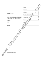
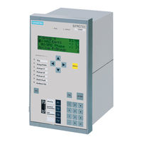
Line Differential Protection with Distance Protection
Brand:
Siemens
| Category:
Relays
| Size: 15.72 MB
Table of Contents
Mounting and Commissioning 3
5
Table of Contents
9
1 Introduction
19
Overall Operation
20
Application Scope
23
Characteristics
27
2 Functions
35
General
37
Functional Scope
37
Configuration of the Scope of Functions
37
Control of the Main Protection Functions
38
Setting Notes
38
Settings
43
General Power System Data (Power System Data 1)
45
Setting Notes
45
Settings
54
Change Group
55
Purpose of the Setting Groups
55
Setting Notes
55
Settings
56
Information List
56
General Protection Data (Power System Data 2)
56
Setting Notes
56
Settings
68
Information List
71
Protection Data Interfaces and Protection Data Topology
74
Functional Description
74
Protection Data Topology / Protection Data Communication
74
Protection Data Interfaces
81
Setting Notes
81
Settings
83
Information List
84
Differential Protection Topology
85
Setting Notes
85
Settings
87
Information List
87
Differential Protection
89
Functional Description
89
Setting Notes
99
Settings
103
Information List
104
Breaker Intertrip and Remote Tripping
106
Functional Description
106
Setting Notes
108
Settings
108
Information List
108
Distance Protection
110
Distance Protection, General Settings
110
Earth Fault Detection
110
Fault Detection (Optional)
113
Calculation of the Impedances
118
Setting Notes
125
Settings
132
Information List
135
Distance Protection with Quadrilateral Characteristic (Optional)
137
Method of Operation
137
Setting Notes
143
Settings
147
Distance Protection with MHO Characteristic (Optional)
150
Functional Description
150
Setting Notes
157
Settings
160
Tripping Logic of the Distance Protection
162
Method of Operation
162
Setting Notes
167
Power Swing Detection (Optional)
168
Method of Operation
168
Setting Notes
174
Settings
174
Information List
174
Teleprotection for Distance Protection (Optional)
175
General
175
Method of Operation
176
PUTT (Pickup)
177
Permissive Underreach Transfer Trip with Zone Acceleration Z1B (PUTT)
179
Direct Underreach Transfer Trip
181
Permissive Overreach Transfer Trip (POTT)
182
Directional Comparison Pickup
185
Directional Unblocking Scheme
187
Directional Blocking Scheme
192
Pilot Wire Comparison
195
Reverse Interlocking
197
Transient Blocking
199
Measures for Weak and Zero Infeed
200
Setting Notes
202
Settings
205
Information List
205
Earth Fault Protection in Earthed Systems (Optional)
207
Method of Operation
207
Setting Notes
219
Settings
228
Information List
231
Teleprotection for Earth Fault Protection (Optional)
232
General
232
Directional Comparison Pickup
233
Directional Unblocking Scheme
236
Directional Blocking Scheme
239
Transient Blocking
242
Measures for Weak or Zero Infeed
243
Setting Notes
244
Settings
248
Information List
248
Weak-Infeed Tripping (Optional)
250
Classical Tripping
250
Method of Operation
250
Setting Notes
253
Tripping According to Specification RTE
253
Functional Description
253
Setting Notes
256
Weak Infeed Tripping (Optional)
257
Settings
257
Information List
258
Direct Local Trip
260
Functional Description
260
Setting Notes
261
Settings
261
Information List
261
Direct Remote Trip and Transmission of Binary Information
262
Functional Description
262
Information List
263
Instantaneous High-Current Switch-Onto-Fault Protection (SOTF)
265
Functional Description
265
Setting Notes
266
Settings
267
Information List
268
Backup Time Overcurrent Protection
269
General
269
Functional Description
269
Setting Notes
275
Settings
281
Information List
282
Automatic Reclosure Function (Optional)
284
Functional Description
285
Setting Notes
301
Settings
309
Information List
312
Synchronism and Voltage Check (Optional)
314
Method of Operation
314
Setting Notes
318
Settings
322
Information List
323
Undervoltage and Overvoltage Protection (Optional)
325
Overvoltage Protection
325
Undervoltage Protection
330
Setting Notes
334
Settings
338
Information List
340
Frequency Protection (Optional)
342
Method of Operation
342
Setting Notes
344
Settings
346
Information List
347
Fault Locator
348
Functional Description
348
Setting Notes
352
Settings
356
Information List
356
Circuit Breaker Failure Protection
358
Functional Description
358
Setting Notes
368
Settings
371
Information List
372
Thermal Overload Protection
373
Method of Operation
373
Setting Notes
374
Settings
376
Information List
376
Monitoring Functions
378
Measurement Supervision
378
Hardware Monitoring Functions
378
Software Monitoring
380
Measuring Circuit Monitoring
381
Malfunction Responses
386
Setting Notes
388
Settings
390
Information List
391
Trip Circuit Supervision
391
Functional Description
392
Setting Notes
395
Settings
395
Information List
395
Function Control and Circuit Breaker Test
396
Function Control
396
Line Energization Recognition
396
Detection of the Circuit Breaker Position
399
Open Pole Detector
402
Pickup Logic for the Entire Device
403
Tripping Logic of the Entire Device
404
Circuit Breaker Test
409
Functional Description
409
Information List
410
Device
411
Trip-Dependent Messages
411
Spontaneous Indications on the Display
411
Switching Statistics
411
Setting Notes
412
Settings
412
Information List
412
Ancillary Functions
414
Commissioning Tools
414
Functional Description
414
Setting Notes
415
Settings
416
Processing of Messages
416
Functional Description
416
Statistics
421
Functional Description
421
Information List
421
Measurement During Operation
423
Functional Description
423
Information List
425
Differential Protection Values
427
Measured Values of the Differential Protection
427
Information List
427
Remote Measured Values
428
Functional Description
428
Measured Values Constellation
429
Functional Description
429
Oscillographic Fault Records
429
Settings
430
Information List
430
Demand Measurement Setup
431
Long-Term Average Values
431
Settings
431
Information List
431
Min/Max Measurement Setup
432
Reset
432
Settings
432
Information List
432
Set Points (Measured Values)
434
Limit Value Monitoring
434
Information List
434
Energy
435
Information List
435
Command Processing
436
Control Authorization
436
Command Types
436
Sequence in the Command Path
437
Switchgear Interlocking
438
Information List
441
Control Device
441
Process Data
442
Method of Operation
442
Information List
442
Protocol
443
Information List
443
3 Mounting and Commissioning
445
Mounting and Connections
446
Configuration Information
446
Hardware Modifications
451
General
451
Disassembly
453
Switching Elements on Printed Circuit Boards
455
Interface Modules
462
Reassembly
466
Mounting
466
Panel Flush Mounting
466
Rack Mounting and Cubicle Mounting
468
Panel Surface Mounting
470
Checking Connections
471
Checking Data Connections of Serial Interfaces
471
Checking the Protection Data Communication
473
Power Plant Connections
474
Commissioning
477
Test Mode / Transmission Block
478
Checking the Time Synchronization Interface
478
Checking the System Interface
479
Checking the States of the Binary Inputs/Outputs
481
Checking the Protection Data Topology
484
Tests for the Circuit Breaker Failure Protection
490
Checking the Instrument Transformer Connections of One Line End
492
Checking the Instrument Transformer Connections of Two Line Ends
494
Checking the Instrument Transformer Connections for more than Two Ends
506
Measuring the Operating Time of the Circuit Breaker
507
Checking the Teleprotection System with Distance Protection
508
Testing the Signal Transmission with Earth Fault Protection
511
Checking the Signal Transmission for Breaker Failure Protection And/Or
513
Stub Fault Protection
513
Checking the Signal Transmission for Internal and External Remote Tripping
513
Testing User-Defined Functions
513
Trip and Close Test with the Circuit Breaker
514
Trip/Close Tests for the Configured Operating Devices
514
Triggering Oscillographic Recordings for Test
515
Final Preparation of the Device
516
4 Technical Data
517
General
519
Analog Inputs
519
Auxiliary Voltage
520
Binary Inputs and Outputs
520
Communications Interfaces
522
Electrical Tests
526
Mechanical Stress Tests
528
Climatic Stress Tests
529
Service Conditions
529
Certifications
530
Mechanical Design
530
Protection Data Interfaces and Differential Protection Topology
531
Differential Protection
533
Breaker Intertrip and Remote Tripping -Direct Local Trip
535
Distance Protection (Optional)
536
System Power Swing (with Impedance) (Optional)
539
Teleprotection for Distance Protection (Optional)
540
Earth Fault Protection in Earthed Systems (Optional)
541
Teleprotection for Earth Fault Protection (Optional)
550
Weak-Infeed Tripping (Classic/Optional)
551
Weak-Infeed Tripping (French Specif./Optional)
552
Direct Remote Trip and Transmission of Binary Information
553
Instantaneous High-Current Switch-Onto-Fault Protection (SOTF)
554
Time Overcurrent Protection
555
Automatic Reclosure Function (Optional)
558
Synchronism and Voltage Check (Optional)
559
Undervoltage and Overvoltage Protection (Optional)
561
Frequency Protection (Optional)
564
Fault Locator
565
Circuit Breaker Failure Protection
566
Thermal Overload Protection
567
Monitoring Function
569
User Defined Functions (CFC)
571
Additional Functions
574
Dimensions
577
Panel Flush and Cubicle Mounting (Housing Size 1 / 2 )
577
Panel Surface Mounting (Housing Size 1 / 2 )
579
Panel Surface Mounting (Housing Size 1 / 1 )
579
Appendix
581
Ordering Information and Accessories
582
Ordering Information
582
Ordering Code (MLFB)
582
A Appendix
582
A.1.2 Accessories
586
Accessories
586
Terminal Assignments
590
Panel Flush Mounting or Cubicle Mounting
590
A.2 Terminal Assignments
590
Panel Surface Mounting
595
Connection Examples
602
Current Transformer Connection Examples
602
A.3 Connection Examples
602
Voltage Transformer Connection Examples
606
Default Settings
609
Leds
609
A.4 Default Settings
609
Binary Input
610
A.4.2 Binary Input
610
Binary Output
611
A.4.3 Binary Output
611
Function Keys
612
Default Display
612
A.4.4 Function Keys
612
Pre-Defined CFC Charts
615
Protocol-Dependent Functions
616
Functional Scope
617
A.6 Functional Scope
617
Settings
619
A.7 Settings
619
Information List
638
A.8 Information List
638
Group Alarms
673
A.9 Group Alarms
673
Measured Values
674
A.10 Measured Values
674
Literature
681
Glossary
683
Index
691
Advertisement
Siemens siprotec 7SD5 Manual (94 pages)
Input/Output unit, Bay control unit, Communication module, PROFIBUS-DP Communication profile
Brand:
Siemens
| Category:
Protection Device
| Size: 0.65 MB
Table of Contents
Preface
3
Revision Index
7
Table of Contents
9
1 PROFIBUS Communication Modules
11
Communication Module Types and Hardware Revisions
12
Communication Module Types
12
Hardware Revisions
12
Compatibility of the Communication Module Hardware with PROFIBUS-DP Firmware Versions and Mapping Files
13
Display of Module-Specific Information at the SIPROTEC Device
15
Block 1: Status and Parameters of the PROFIBUS-DP Slave
17
Block 2: Firmware Versions and Mapping File
19
Block 3: Module Hardware Information and Boot Firmware Version
20
Block 4: OLM Information
21
Block 5: Status of the Event List Via PROFIBUS-DP
24
2 Parameters and Properties
25
Bus Specific Parameters
26
PROFIBUS-DP Settings
26
Configuration of the Fibre-Optical Interface
28
Event List Settings
31
PROFIBUS-DP Configuration Data
31
Execution of Switching Operations Via PROFIBUS-DP
32
Command Output Modes
32
Transformer Tap Change Commands
33
Behaviour under Special Operating Conditions
33
Response in the Event of Disturbed Communication to the PROFIBUS-DP Master
34
Communication Interruption
34
Signalling of Line-Breaks in a Redundant Fibre-Optical Ring
35
Annunciations to the PROFIBUS-DP Master
37
Event List Via PROFIBUS-DP (Sequence of Events Recorder)
38
Properties of the Event List
39
Structure of a PROFIBUS-DP Telegram with Event List
40
Telegram in Input Direction
40
Telegram in Output Direction
42
Handshake Mechanism
43
3 Data Type Definitions
45
Single-Point Indication (SP, Input)
46
Single Command (SC, Output)
47
Double-Point Indication (DP, Input) / Double Command (DC, Output)
48
Measured Value (Signed Integer)
49
Measured Value (Float)
50
Metered Measurand (Unsigned Long)
51
Transformer Tap Change Command (TC)
52
Transformer Tap Position Indication (TM)
53
Message Block for Event List Via PROFIBUS-DP
54
4 PROFIBUS-DP - Parameterization in DIGSI
57
Interface Selection and Mapping Files
58
Standard Mappings 3-1 to 3-N
58
Compatibility with Standard Mappings of Previous Versions
59
Interface Selection and Mapping Selection in DIGSI 4.21
59
Interface Selection and Mapping Selection in DIGSI 4.3 or Higher
63
Customization of the Allocations
66
Scaling of Measured Values
70
Measurement Conversion
70
Number Representation Depending on the Parameterization
71
Parameterization in DIGSI
73
Time Synchronization
75
PROFIBUS-DP Master
75
Parameterization in DIGSI
77
Using SFC14 and SFC15 in STEP7
79
5 Technical Data
83
Connection Via the PSE Module
84
Connection Via the PSO Module
86
Glossary
89
Index
91
Advertisement
Related Products
Siemens SIPROTEC 7SD610
Siemens 7SD502
Siemens Argus 7SR21
Siemens Argus 7SR12
Siemens SIPROTEC 7SA511
Siemens 7SR45 Argus
Siemens SIPROTEC 7SJ62
Siemens 7SR23 DAD
Siemens 7SG16 Ohmega 402-60
Siemens 7SG164 Ohmega 400 Series
Siemens Categories
Industrial Equipment
Controller
Control Unit
Oven
Washer
More Siemens Manuals
Login
Sign In
OR
Sign in with Facebook
Sign in with Google
Upload manual
Upload from disk
Upload from URL