Sign In
Upload
Manuals
Brands
Siemens Manuals
Relays
siprotec 7SJ63
Siemens siprotec 7SJ63 Manuals
Manuals and User Guides for Siemens siprotec 7SJ63. We have
3
Siemens siprotec 7SJ63 manuals available for free PDF download: Instruction Manual, Manual, Technical Data Manual
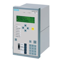
Siemens siprotec 7SJ63 Instruction Manual (604 pages)
Multi-Functional Protective Relay with Local Control
Brand:
Siemens
| Category:
Relays
| Size: 9.35 MB
Table of Contents
C53000-G1140-C120
2
Table of Contents
7
1 Introduction
17
Overall Operation
18
Applications
21
Characteristics
23
Scope of Functions
24
2 Hardware and Connections
29
Version of 7SJ63 for Panel Flush-Mounting / Cubicle Mounting
30
Construction
30
Connections to Threaded Terminals
35
Connections to Plug-In Terminals
39
Connections to Optical Communication Interfaces
42
Connections to Electrical Communication Interfaces
43
Version of 7SJ63 for Panel Surface-Mounting
44
Construction
44
Connections to Threaded Terminals
47
Connections to Optical Communication Interfaces
47
Version of 7SJ63 with a Detached Operator Panel
49
Construction
49
Connections to Threaded Terminals
51
Connections to Plug-In Terminals
55
Connections to Optical Communication Interfaces
58
Connections to Electrical Communication Interfaces
59
3 Initial Inspections
61
Unpacking and Packing
62
Inspections Upon Receipt
63
Inspection of Features and Ratings
63
Electrical Check
63
User Interface
65
Navigating through the Operating Menus Using the Operator Control Panel
65
Operation Using DIGSI ® 4
68
Storage
73
4 SIPROTEC 4 Devices
75
General
76
Protection and Control
76
Communication
77
Settings
78
Operations
78
Waveform Capture
78
Operator Control Facilities
79
Operating Panel on Device
79
Digsi
82
DIGSI ® 4 Tool
82
Information Retrieval
83
Annunciations
84
Measurements
86
Waveform Capture
88
Control
89
Manual Overwrite / Tagging
91
General Setting Procedure
92
Device Configuration
95
Configuration of Inputs and Outputs (Configuration Matrix)
96
Display Editor
99
Default Display
99
Control Display
99
Programmable Logic CFC
101
Power System Data
103
Setting Groups
104
General Device Settings
106
Time Synchronization
107
Serial Interfaces
108
Passwords
110
5 Configuration
113
Configuration of Functions
114
Configuration of Information, Meaured Values, and Commands
118
Preparation
118
Structure and Operation of the Configuration Matrix
124
Establishing Information Properties
128
Performing Configuration
135
Transferring Metering Values
143
Setting of Contact Chatter Blocking
144
Creating User Defined Functions with CFC
146
Establishing a Default Display
154
Establishing a Control Diagram
157
Serial Ports
159
Date and Time Stamping
162
6 Functions
165
General
167
Settings
168
Power System Data 1
172
Information
176
Information
178
Information
181
Overcurrent Protection (50, 50N, 51, 51N)
182
Description of Instantaneous Overcurrent Protection
182
Definite Time, Instantaneous Overcurrent Protection (50, 50N)
182
Inverse Time-Overcurrent Protection (51, 51N)
186
Reverse Interlocking Bus Protection
189
Programming Time-Overcurrent Settings
190
Programming Settings for Time-Overcurrent Phase Protection
190
Settings for Phase Overcurrent Protection
196
Information List for Phase Overcurrent Protection
198
Programming Settings for Time-Overcurrent Ground Protection
198
Settings for Ground Overcurrent Protection
201
Information List for Ground Overcurrent Protection
202
Directional Overcurrent Protection (67, 67N)
204
Description of Directional Overcurrent Protection
206
Definite Time, Directional Overcurrent Protection
206
Inverse Time, Directional Overcurrent Protection (67-TOC, 67N-TOC)
208
Determination of Direction
209
Reverse Interlocking for Looped Lines
212
Programming Directional Overcurrent Settings
213
Programming Settings for Directional Overcurrent Phase Protection
213
Settings for Directional Phase Overcurrent Protection
218
Information List for Directional Phase Overcurrent Protection
220
Programming Settings for Directional Overcurrent Ground Protection
221
Settings for Directional Ground Overcurrent Protection
223
Information List for Directional Ground Overcurrent Protection
224
Dynamic Cold Load Pick-Up Function (50C, 50Nc, 51Nc, 67C, 67Nc)
226
Description of Dynamic Cold Load Pick-Up Function
226
Programming Settings
228
Settings for Dynamic Cold Load Adjustments
229
Information List for Dynamic Cold Load Setting Adjustments
232
Inrush Restraint
233
Description of Inrush Restraint
233
Programming Settings
235
Settings for Inrush Restraint (Stabilization)
235
Information List for Inrush Restraint (Stabilization)
236
Sensitive Ground Fault Detection (64, 50Ns, 67Ns)
237
Description of Sensitive Ground Fault Detection
237
Voltage Element
237
Current Elements
238
Determination of Direction
238
Location of Ground Connections
242
Programming Settings
243
Settings for Sensitive Ground Fault Detection
247
Information List for Sensitive Ground Fault Detection
249
Negative Sequence Protection (46)
250
Description of Negative Sequence Protection
250
Determination of Unbalanced Load
250
Definite Time Elements (46-1, 46-2)
250
Inverse Time Element (46-TOC)
251
Programming Settings
253
Settings for Negative Sequence (Phase Balance) Current Protection
255
Information List for Negative Sequence Current Protection
257
Motor Starting Protection (48)
258
Description of Motor Starting Protection
258
Programming Settings
260
Settings for Motor Starting Time Monitoring
261
Information List for Motor Starting Time Monitoring
262
Thermal Overload Protection (49)
263
Description of Thermal Overload Protection
263
Programming Settings
265
Settings for Thermal Overload Protection
268
Information List for Thermal Overload Protection
269
Start Inhibit for Motors (66/68)
270
Description of Start Inhibit for Motors
270
Programming Settings
272
Settings for Start Inhibit of Motors
273
Information List for Start Inhibit of Motors
274
Voltage Protection (27, 59)
275
Description of Voltage Protection
275
Measurement Principle
275
Overvoltage Protection (59)
275
Undervoltage Protection (27)
276
Programming Settings
279
Overvoltage Protection
280
Settings for Overvoltage Protection
280
Information List for Overvoltage Protection
280
Undervoltage Protection
281
Settings for Undervoltage Protection
282
Information List for Undervoltage Protection
283
Frequency Protection (81 O/U)
284
Description of Frequency Protection
284
Programming Settings
285
Settings for Frequency Protection
286
Information List for Frequency Protection
287
Breaker Failure Protection (50BF)
288
Description of Breaker Failure Protection
288
Programming Settings
291
Settings for Breaker Failure Protection
292
Information List for Breaker Failure Protection
292
Automatic Reclosing System (79M)
293
Description of Automatic Reclosing System
293
Programming Settings
299
Settings for Automatic Reclosing
301
Information List for Automatic Reclosing
306
Fault Location
307
Description of Fault Location
307
Setting the Functional Parameters
309
Settings for Fault Locator
310
Information List for Fault Location
310
Phase Rotation
311
Description of Phase Rotation
311
Programming Settings
311
Monitoring Functions
312
Description of Measured Values Monitoring
312
Hardware Monitoring
312
Software Monitoring
313
Monitoring of External Current Transformer Circuits
314
Xqfwlrqv
314
Programming Settings for Measured Values Monitoring
315
Settings for Measured Values Monitoring
316
Information
317
Description of Fuse-Failur-Monitor
317
Programming Settings for Fuse-Failure-Monitor
318
Settings for Fuse-Failure-Monitor
318
Information
318
Description of Trip Circuit Monitor (74TC)
318
Programming Settings for Trip Circuit Monitor
321
Setting for Trip Circuit Monitor
323
Information
323
Malfunction Responses of the Monitoring Functions
324
Protection Function Logic
326
Pickup Logic for the Entire Device
326
Tripping Logic of the Entire Device
326
Programming Settings for Tripping Logic
327
Fault Display on the Leds/Lcd
327
Programming Settings
328
Statistical Counters
328
Setting/Resetting
328
Information List for the Device
329
Auxiliary Functions
330
Message Processing
330
Measurements
331
Waveform Capture
333
Programming Settings
334
Settings for Auxiliary Functions
336
Information List for Auxiliary Functions
337
Breaker Control
338
Types of Commands
339
Steps in the Command Sequence
340
Interlocking
341
Interlocked/Non-Interlocked Switching
342
7 Operators Tools
347
Retrieval of Information
348
Messages
348
Output of Messages
348
Event Log (Operating Messages)
350
Trip Log (Fault Messages)
352
Ground Fault Messages (Ground Fault Messages Associated with the Sensitive Ground Fault Function)
354
Saving and Erasing the Messages
355
General Interrogation
357
Spontaneous Messages
357
Statistics
358
Retrieve the Statistics
358
Resetting and Setting the Statistics
359
Setting Limit Values for the Statistics Counters
360
Measured and Metered Values
361
Measured Values
362
Energy, Metered Values
367
Setting Limit Values
368
Resetting Metered Values and Min/Max Values
370
Waveform Capture
371
Retrieving of Waveform Capture
371
Saving of Waveform Capture
373
Control of Device Functions
374
Display and Set Date and Time
374
Changeover of Setting Groups
378
Test Messages to the SCADA Interface During Test Operation
381
Control of Switchgear
384
Display Equipment Position and Control
385
Manual Overwriting
388
Set Status
389
Interlocking
391
Tagging
392
Switching Authority
393
Switching Mode
393
Control Messages
394
Other Commands
396
8 Installation and Commissioning
397
Installation and Connections
398
Installation
398
Connections
402
Hardware Modifications
404
Checking Connections
415
Data Connections
415
Power Plant Connections
416
Commissioning
419
Current, Voltage, and Phase Rotation Testing
419
Directional Testing with Load Current
420
Polarity Testing for Ground Fault Protection
421
Testing the Reverse Interlocking Scheme (if Applicable)
423
Testing the Breaker Failure Scheme (if Applicable)
425
Testing User-Defined Functions
425
Test Mode and Blocking Data Transmission
426
Checking the Binary Inputs and Outputs
426
Trip/Close Tests for Primary Equipment
428
Triggering Oscillographic Recordings
428
Generate Indications
429
Final Preparation of the Device
432
9 Routine Checks and Maintenance
433
General
434
Routine Checks
435
Maintenance
436
Replacing the Battery
436
Battery Replacement for Flush Mount and Surface Mount Devices
436
Battery Replacement for a Device with Detached Faceplate
438
Troubleshooting
440
Corrective Action/Repairs
442
Software Procedures
442
Hardware Procedures
442
Return
446
10 Technical Data
447
General Device Data
448
Analog Inputs and Outputs
448
Power Supply
448
Binary Inputs and Outputs
449
Communications Interfaces
451
Electrical Tests
453
Mechanical Stress Tests
455
Climatic Stress Tests
456
Service Conditions
456
Construction
457
Definite-Time Overcurrent Protection (50 and 50N Elements)
458
Inverse-Time Overcurrent Protection (51 and 51N Elements)
459
Directional Time Overcurrent Protection (67 and 67N Elements)
465
Dynamic Cold Load Pick-Up Function (50C, 50Nc, 51Nc, 67C, 67Nc)
466
Inrush Restraint
466
Sensitive Ground Fault Detection (64, 50Ns, 67Ns)
467
Negative Sequence Protection (46)
469
Definite-Time Elements (46-1 and 46-2)
469
Inverse-Time Elements (46-TOC)
469
Motor Starting Protection (48)
474
Thermal Overload Protection (49)
475
Start Inhibit for Motors (66/68)
477
Voltage Protection (27 and 59)
478
Frequency Protection (81 Over-Frequency and Under-Frequency)
479
Breaker Failure Protection (50BF)
480
Automatic Reclosing System (79M)
481
Fault Location
482
Breaker Control
482
Additional Functions
483
Dimensions
487
Appendix
495
Ordering Information and Accessories
496
Accessories
498
A.1.1 Accessories
498
Elementary Diagrams (V4.1
500
Housing for Panel Flush Mounting or Cubicle Installation
500
Housing for Panel Surface Mounting
505
Devices with Detached Operation Unit
512
Elementary Diagrams (V4.0
517
Housing for Panel Flush Mounting or Cubicle Installation
517
A Appendix
519
Housing for Panel Surface Mounting
522
Devices with Detached Operation Unit
529
Connection Examples
534
A.4 Connection Examples
534
Settings
542
A.5 Settings
542
Interoperability List
553
A.6 Interoperability List
553
Information List
555
A.7 Information List
555
Overview of the Masking Features of the User Defined Informations
590
Default Settings
594
Pre-Defined Control Diagram
594
A.9 Default Settings
594
Pre-Defined CFC Charts
595
Index
604
Advertisement
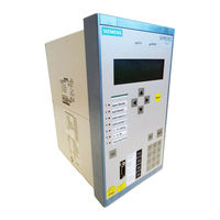
Siemens siprotec 7SJ63 Manual (94 pages)
Input/Output unit, Bay control unit, Communication module, PROFIBUS-DP Communication profile
Brand:
Siemens
| Category:
Protection Device
| Size: 0.65 MB
Table of Contents
Preface
3
Revision Index
7
Table of Contents
9
1 PROFIBUS Communication Modules
11
Communication Module Types and Hardware Revisions
12
Communication Module Types
12
Hardware Revisions
12
Compatibility of the Communication Module Hardware with PROFIBUS-DP Firmware Versions and Mapping Files
13
Display of Module-Specific Information at the SIPROTEC Device
15
Block 1: Status and Parameters of the PROFIBUS-DP Slave
17
Block 2: Firmware Versions and Mapping File
19
Block 3: Module Hardware Information and Boot Firmware Version
20
Block 4: OLM Information
21
Block 5: Status of the Event List Via PROFIBUS-DP
24
2 Parameters and Properties
25
Bus Specific Parameters
26
PROFIBUS-DP Settings
26
Configuration of the Fibre-Optical Interface
28
Event List Settings
31
PROFIBUS-DP Configuration Data
31
Execution of Switching Operations Via PROFIBUS-DP
32
Command Output Modes
32
Transformer Tap Change Commands
33
Behaviour under Special Operating Conditions
33
Response in the Event of Disturbed Communication to the PROFIBUS-DP Master
34
Communication Interruption
34
Signalling of Line-Breaks in a Redundant Fibre-Optical Ring
35
Annunciations to the PROFIBUS-DP Master
37
Event List Via PROFIBUS-DP (Sequence of Events Recorder)
38
Properties of the Event List
39
Structure of a PROFIBUS-DP Telegram with Event List
40
Telegram in Input Direction
40
Telegram in Output Direction
42
Handshake Mechanism
43
3 Data Type Definitions
45
Single-Point Indication (SP, Input)
46
Single Command (SC, Output)
47
Double-Point Indication (DP, Input) / Double Command (DC, Output)
48
Measured Value (Signed Integer)
49
Measured Value (Float)
50
Metered Measurand (Unsigned Long)
51
Transformer Tap Change Command (TC)
52
Transformer Tap Position Indication (TM)
53
Message Block for Event List Via PROFIBUS-DP
54
4 PROFIBUS-DP - Parameterization in DIGSI
57
Interface Selection and Mapping Files
58
Standard Mappings 3-1 to 3-N
58
Compatibility with Standard Mappings of Previous Versions
59
Interface Selection and Mapping Selection in DIGSI 4.21
59
Interface Selection and Mapping Selection in DIGSI 4.3 or Higher
63
Customization of the Allocations
66
Scaling of Measured Values
70
Measurement Conversion
70
Number Representation Depending on the Parameterization
71
Parameterization in DIGSI
73
Time Synchronization
75
PROFIBUS-DP Master
75
Parameterization in DIGSI
77
Using SFC14 and SFC15 in STEP7
79
5 Technical Data
83
Connection Via the PSE Module
84
Connection Via the PSO Module
86
Glossary
89
Index
91
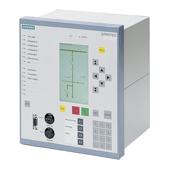
Siemens siprotec 7SJ63 Technical Data Manual (58 pages)
Multifunction protection with control
Brand:
Siemens
| Category:
Control Unit
| Size: 0.26 MB
Table of Contents
Table of Contents
7
1 Bus Specific Parameters
11
2 Supported Modbus Functions
13
Table 2-1 Supported Modbus Functions
14
3 Exception Responses of the Modbus Slave
15
4 Annunciations to the Modbus Master
17
5 Data Type Definitions
19
Single Command (SC) / Single-Point Indiation (SP)
20
Double Command (DC) / Double-Point Indication (DP)
20
Figure 5-1 Data Typ Single Command / Single-Point Indication
20
Figure 5-2 Data Type Double Command / Double-Point Indication
20
Measured Value (Signed Integer)
21
Metered Measurand (Unsigned Long)
21
Figure 5-3 Data Type Measured Value (Signed Integer)
21
Figure 5-4 Data Type Metered Measurand (Unsigned Integer)
21
6 Modbus Register Map
23
Explanation
23
Notes for Parametrization in DIGSI
24
Coil Status Registers (0X References)
25
Register Addresses 00001 to 00018: Double Commands
25
Register Addresses 00033 to 00054: Single Commands
26
Register Addresses 00065 to 00071: Internal Commands
27
Register Addresses 00081 to 0096: Application Logic CFC
28
Register Addresses 00257 to 00264: Exception Flags
30
Input Status Registers (1X References)
31
Register Addresses 10001 to 10037: Input Channels with Allocation to the Binary Inputs
31
Register Addresses 10049 to 10064: Application Logic CFC
32
Register Addresses 10065 to 10089: Automatic Recloser Status
33
Register Addresses 10097 to 10137: Time Overcurrent Protection
34
Register Addresses 10145 to 10188: Directional Time Overcurrent Protection
35
Register Addresses 10193 to 10200: Unbalanced Load Protection
37
Register Addresses 10209 to 10224: Frequency Protection
37
Register Addresses 10225 to 10247: Undervoltage and Overvoltage Protection
38
Register Addresses 10257 to 10278: Sensitive Ground Fault Protection
39
Register Addresses 10289 to 10298: Circuit Breaker Failure Protection
40
Register Addresses 10305 to 10313: Thermal Overload Protection
40
Register Addresses 10321 to 10325: Motor Start Protection
40
Register Addresses 10337 to 10342: Startup Supervision
41
Register Addresses 10353 to 10359: Trip Coil Monitor
41
Register Addresses 10369 to 10383: Inrush Stabilization
41
Register Address 10385: Fault Locator
42
Register Addresses 10393 to 10396: Cold Load Pickup
42
Register Addresses 10401 to 10408: Measurement Supervision
43
Register Addresses 10417 to 10426: Set Point Alarms
43
Register Addresses 10433 to 10446: Status Annunciations
43
Input Registers (3X References)
45
Reference Values for Selecting a Standard Mapping in Accordance with the Operating Values of the Primary Equipment
45
Recorded Measured Values
46
Holding Registers (4X References)
48
Register Addresses 40001 to 40048: System Information
48
Register Address 40129: Diagnosis
48
Register Addresses 40201 to 40215: Metered Measurands
50
Register Addresses 40251 to 40257: Measured Values - Mean Values
51
Register Addresses 40301 to 40305: Fault Locator and Fault Currents
52
7 Technical Data
53
Modbus Slave for the SIPROTEC Devices
53
Hardware Interface
53
Connection Via the AME Module
54
Connection Via the AMO Module
54
Table 7-1 Technical Data of the Connection Via the AME Module
54
Table 7-2 Assignment of the Bus Connection at the Device (D-SUB Outlet)
54
Table 7-3 Technical Data of the Connection Via the AMO Module
54
8 Glossary
55
9 Index
57
Advertisement
Advertisement
Related Products
Siemens siprotec 7sj602
Siemens SIPROTEC 7SJ600
Siemens SIPROTEC 7SJ62
Siemens 7SJ511
Siemens SIPROTEC 7SJ81
Siemens Argus 7SR22
Siemens 7SR242 Duobias
Siemens 7SR1003 Argus
Siemens 7SR1002 Argus
Siemens SIPROTEC 7SK81
Siemens Categories
Industrial Equipment
Controller
Control Unit
Oven
Washer
More Siemens Manuals
Login
Sign In
OR
Sign in with Facebook
Sign in with Google
Upload manual
Upload from disk
Upload from URL