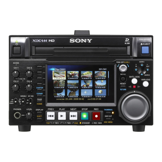
Sony PDW-HD1500 Installation Manual
Professional disc recorder
Hide thumbs
Also See for PDW-HD1500:
- Operation manual (193 pages) ,
- Maintenance manual (160 pages) ,
- Brochure & specs (28 pages)
Table of Contents
Advertisement
Quick Links
Advertisement
Table of Contents

Summary of Contents for Sony PDW-HD1500
- Page 1 PROFESSIONAL DISC RECORDER PDW-HD1500 INSTALLATION MANUAL 1st Edition...
- Page 2 Pour toute réparation faire appel à une personne compétente uniquement. For safety, do not connect the connector for peripheral device wiring that might have excessive voltage to the following port(s). : NETWORK connector Follow the instructions for the above port(s). PDW-HD1500 IM...
- Page 3 Hävitä käytetty paristo valmistajan ohjeiden Remplacer uniquement avec une batterie du même mukaisesti. type ou d’un type équivalent recommandé par le constructeur. Mettre au rebut les batteries usagées conformément aux instructions du fabricant. 1 (P) PDW-HD1500 IM...
- Page 4 Top: 2 cm (1 inches) or more Right, Left: 2 cm (1 inches) or more Rear: 25 cm (10 inches) or more This label is located on the top panel of the drive unit. 2 (P) PDW-HD1500 IM...
-
Page 5: Table Of Contents
Outside Dimensions ........1-4 (E) 1-5-2. Notes on Installation ........1-5 (E) 1-5-3. Rack Mounting ..........1-6 (E) 1-6. Connectors/Cables ........... 1-7 (E) 1-7. Signal Inputs and Outputs ........1-8 (E) 1-8. Settings after Installation ........1-11 (E) 1 (E) PDW-HD1500 IM... -
Page 7: Manual Structure
Manual Structure Purpose of this manual This manual is the installation manual of Professional Disc Recorder PDW-HD1500. This manual is intended for use by trained system and service engineers, and describes the information on installing the PDW-HD1500. Related manuals Besides this Installation Manual, the following manuals are prepared for PDW- HD1500. -
Page 9: Installation
Operation manual (Japanese) ..........1 Operation manual (English) ..........1 Installation manual ............1 CD-ROM (Operation manual) ........... 1 CD-ROM (XDCAM APPLICATION SOFTWARE) ..1 After installation, be sure to use the supplied cap for protecting unused connector. 1-1 (E) PDW-HD1500 IM... -
Page 10: Operating Conditions
. Areas with strong magnetic field. . Areas with much electrical noise. . Areas with much static electricity. . Areas that is impossible to find a specified room for installation. (Refer to Section “1-5. Installation Space” .) . Areas windtight. 1-2 (E) PDW-HD1500 IM... -
Page 11: Power Supply
When the battery is nearly dead, the battery indicator on the left side of the LCD panel will blink. For details, refer to the operation manual supplied with the unit. DC power cord Lithium-ion battery Battery adaptor BP-GL95 BKP-L551 BP-L80S PDW-HD1500 Rear view 1-3 (E) PDW-HD1500 IM... -
Page 12: Installation Space
1-5. Installation Space 1-5-1. Outside Dimensions 373.3 396.4 Unit: mm 1-4 (E) PDW-HD1500 IM... -
Page 13: Notes On Installation
Attaching Position of the Battery Adapter Install the battery adapter by screwing two screws into the holes on the left side of the unit. Regarding installation, refer to the operation manual. Screw holes PDW-HD1500 Left side view 1-5 (E) PDW-HD1500 IM... -
Page 14: Rack Mounting
. Do not cover the exhaust port or ventilation holes (lower front, right and left sides). . When installing units side by side, leave 1 cm or more of space to the both side of each PDW-HD1500. Blocking the air intake will damage the unit. -
Page 15: Connectors/Cables
RCC-5G (5 m)/10G (10 m)/30G (30 m) PHONES JM-60 stereo phone plug (commercially available) S400 (i.LINK) IEEE1394 6P STP cable is recommented. (STP: Shielded Twist Pair) (NETWORK) RJ-45 8P 1000BASE-T standard conformity article UTP cable is recommented. (UTP: Unshielded Twist Pair) 1-7 (E) PDW-HD1500 IM... -
Page 16: Signal Inputs And Outputs
REMOTE (9P) D-SUB 9P connector x1 (RS-422A interface) Remote control S400 (i.LINK) 6P, Conform to IEEE1394, Correspond to S400 NETWORK RJ-45 8P modular jack 10BASE-T (Conform to IEEE802.3i) 100BASE-TX (Conform to IEEE802.3u) 1000BASE-T (Conform to IEEE802.3ab) 1-8 (E) PDW-HD1500 IM... - Page 17 BNC x2 (1 set: CH1/2, CH3/4) OUT (AES/EBU) Digital audio AES/EBU format, Conform to AES-3id-1995 PHONES JM-60 stereo phone jack (at the front) Analog audio up to _13 dBu adjustable (8 Z load), unbalanced Other MAINTENANCE High-Speed USB (USB2.0) x2 1-9 (E) PDW-HD1500 IM...
- Page 18 Pin No. Signal (External View) VPC_TX (_) (Output) Pin No. Signal VPC_RX (+) (Input) EXT DC VPC_TX (+) (Output) VPC_RX (_) (Input) 3 REMOTE: 4-pin (female) (External View) Pin No. Signal UNREG GND UNREG +12 V 1-10 (E) PDW-HD1500 IM...
-
Page 19: Settings After Installation
For the settings after installation, refer to the operation 2 4 6 manual. 1 3 5 (External View) Pin No. Signal Specifications BUS POWER NTPB STROBE B (_) STROBE B (+) NTPA DATA A (_) DATA A (+) 1-11 (E) PDW-HD1500 IM... - Page 21 : The material contained in this manual consists of information that is the property of Sony Corporation. Check the metal trim, “metallized” knobs, screws, Sony Corporation expressly prohibits the duplication of...
- Page 22 Printed in Japan Sony Corporation PDW-HD1500 (SY) J, E 2008. 2 16 3-398-656-01 ©2008...


