Advertisement
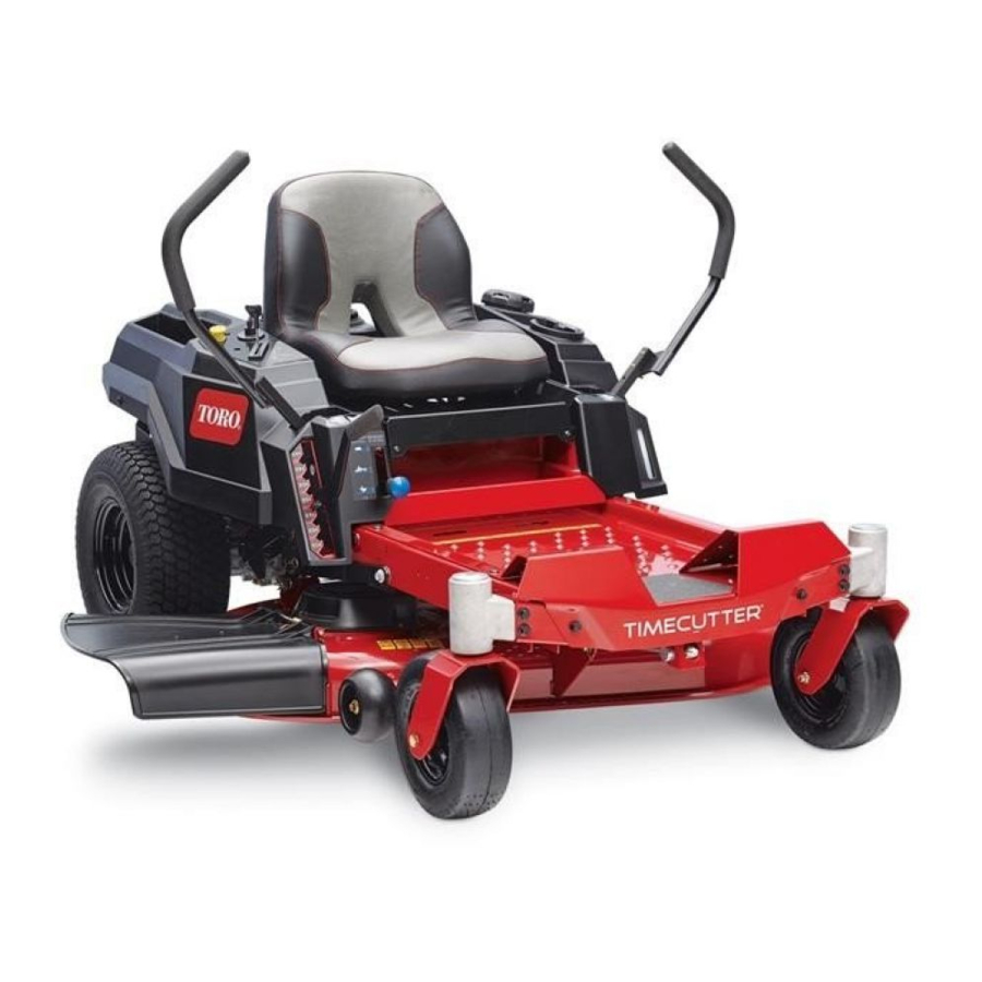
TimeCutter
For TimeCutter
Setup
Loose Parts
Use the chart below to verify that all parts have been shipped.
Procedure
1
2
3
4
5
6
7
Note:
Determine the left and right sides of the machine from the normal operating position.
© 2018—The Toro® Company
8111 Lyndale Avenue South
Bloomington, MN 55420
®
Riding Mowers
®
Riding Mowers with MyRide
Description
Pin
Round clip
No parts required
No parts required
Rear hitch
Bolt (5/16 x 1 inch)
Locknut (5/16 inch)
No parts required
No parts required
Ignition key
Hose coupling (not included with CE
models)
Operator's Manual
Engine owner's manual (non-Toro
engines)
Operator training material
Register at www.Toro.com.
Form No. 3420-276 Rev B
®
Suspension
Qty.
1
Install the MyRide suspension.
2
–
Connect the battery.
Install the seat (machines with MyRide
–
suspension and shipped in a wood crate
only).
1
2
Install the rear hitch.
2
–
Set up the motion-control levers.
–
Check the mower adjustment.
1
1
1
Completing the setup.
1
1
Original Instructions (EN)
All Rights Reserved *3420-276* B
Printed in the USA
Use
Advertisement
Table of Contents

Summary of Contents for Toro TimeCutter series
-
Page 1: Loose Parts
Ignition key Hose coupling (not included with CE models) Operator's Manual Completing the setup. Engine owner’s manual (non-Toro engines) Operator training material Note: Determine the left and right sides of the machine from the normal operating position. © 2018—The Toro® Company Register at www.Toro.com. - Page 2 Installing the MyRide ® Suspension Machines with MyRide Suspension and Shipped in a Wood Crate Only Parts needed for this procedure: Round clip Procedure Raise the platform and remove the wooden g233947 block from above the battery. Figure 2 Note: You can discard the wooden block.
-
Page 3: Connecting The Battery
Connecting the Battery Installing the Seat Machines with MyRide Suspension No Parts Required and Shipped in a Wood Crate Only Procedure No Parts Required Locate the battery and negative battery cable. Remove the plastic cap from the negative Procedure battery post. Remove the 2 hairpin cotters from the seat-pivot Remove the fasteners on the negative battery rod, and remove the seat-pivot rod from the... - Page 4 Place the seat assembly onto the platform Install a hairpin cotter on 1 side of the seat-pivot (Figure rod, then slide the seat-pivot rod through the pivot bracket hole and seat pan hole (Figure g233953 Figure 7 Install the other hairpin cotter on the other side of the seat-pivot rod (Figure g233955...
- Page 5 Rotate the seat assembly upward and connect the wire harness to the seat switch on the bottom of the seat (Figure g015398 Figure 11 After assembly g233951 Figure 9 1. Seat switch Installing the Rear Hitch Parts needed for this procedure: Rear hitch Bolt (5/16 x 1 inch) Locknut (5/16 inch)
-
Page 6: Setting Up The Motion-Control Levers
No Parts Required Hose coupling (not included with CE models) Procedure Operator's Manual Engine owner’s manual (non-Toro engines) Locate the motion-control levers attached, but folded down on the machine. Operator training material Remove the upper bolt (3/8 x 1 inch) and washer;... - Page 7 Notes:...


