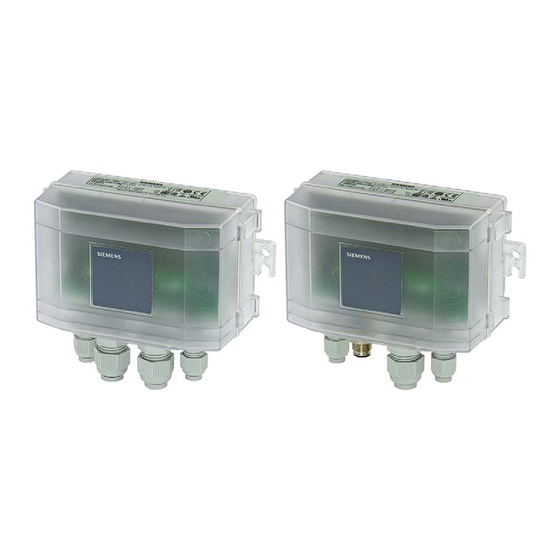
Summary of Contents for Siemens QBM97 Series
- Page 1 Modbus air pressure sensor with I/O extension QBM97.. User Guide Building Technologies A6V11478123_en_a 2019-02-01...
-
Page 2: Table Of Contents
Baud rate ..................13 Fault detection, correction or reset ..............14 Engineering ....................15 Implementing volume flow measurement............15 Modbus registers ................... 16 Maintenance ....................20 Zero reset ...................... 20 Additional information ................21 2 | 22 Siemens A6V11478123_en_a Building Technologies 2019-02-01... -
Page 3: Legal Note
Safety notes in the data sheet NOTICE Comply with all safety notes in data sheet A6V11478118 in the sections "Technical data" and "Notes". 3 | 22 A6V11478123_en_a Siemens Building Technologies 2019-02-01... -
Page 4: Installation
Proceed as follows to mount the sensor to a surface: ● Screw the sensor at the 2 brackets (on the device sides) to the mounting surface. ● Keep the following guidelines min. 75 All measurements in millimeters 4 | 22 Siemens A6V11478123_en_a Building Technologies 2019-02-01... -
Page 5: Dimensions
Installation Mounting 1.1.1 Dimensions QBM97.. (all dimensions in mm) 9 10 Front view QBM97.. (here: without M12) Side view QBM97.. (here: without M12) Bottom view QBM97.. (opened cover) AQB9120/101A and AQB9220/101A 5 | 22 A6V11478123_en_a Siemens Building Technologies 2019-02-01... -
Page 6: Quick Release Fasteners And Detached Cover
Installation Quick release fasteners and detached cover 1.2 Quick release fasteners and detached cover ● Open the housing with the quick release fasteners ● The cover can easily be detached completely 90° 6 | 22 Siemens A6V11478123_en_a Building Technologies 2019-02-01... -
Page 7: Connecting Tubes
Installation Connecting tubes 1.3 Connecting tubes Connect the tubes Avoid loops 7 | 22 A6V11478123_en_a Siemens Building Technologies 2019-02-01... -
Page 8: Wiring
Climatix controller and QBM97 are connected to the same power source, take care to avoid miswiring between 24 V input and GND The document "Modbus communication" (J3960) provides profound information on Modbus grounding. 8 | 22 Siemens A6V11478123_en_a Building Technologies 2019-02-01... -
Page 9: Power Supply
Installation Wiring 1.4.2 Power supply Terminal 24V≂ →, ,24V≂ ← Diagram Note Earth is optional. 9 | 22 A6V11478123_en_a Siemens Building Technologies 2019-02-01... -
Page 10: Signal Wiring
Connecting passive temperature sensors. Signal types: Pt1000, LG-Ni1000, NTC10k and Ni1000 Terminal AI1, AI2 Diagram Analog inputs for voltage signal Connecting devices that supply a 0…10 V signal Terminal AI1, AI2 Diagram 10 | 22 Siemens A6V11478123_en_a Building Technologies 2019-02-01... - Page 11 Installation Wiring 1.4.3.2 Analog outputs Analog outputs with voltage signal Connecting devices that are controlled with a 0...10 V signal Terminal AO1, AO2 Diagram 11 | 22 A6V11478123_en_a Siemens Building Technologies 2019-02-01...
-
Page 12: Commissioning
0: Off ● The termination is done with 120 Ω + 1nF. ● Even if the addressing is done with "On-event addressing (Climatix controllers) [➙ 13]", the termination has to be done manually. 12 | 22 Siemens A6V11478123_en_a Building Technologies 2019-02-01... -
Page 13: On-Event Addressing (Climatix Controllers)
The default value of the QBM97.. Modbus baudrate is "Auto". That means the QBM97.. takes over the baud rate of the calling device. The first connection to the QBM97.. can last up to 30 seconds (to process the auto baud function). 13 | 22 A6V11478123_en_a Siemens Building Technologies 2019-02-01... -
Page 14: Fault Detection, Correction Or Reset
Use the push button to do a reset to factory setting. The Sensor is reset to delivered setting. Factory settings are listed in the register list "Modbus registers [➙ 16]" – default values. Hold the push button for 20…30 seconds. 14 | 22 Siemens A6V11478123_en_a Building Technologies 2019-02-01... -
Page 15: Engineering
Value in register "flow high" = 12 ● Value in register "flow low" = 35012 Calculation: 12*65536 = 786432 786432 + 35012 = 821444 With scaling (0.01) the end value = 8214.44m3/h. 15 | 22 A6V11478123_en_a Siemens Building Technologies 2019-02-01... -
Page 16: Modbus Registers
Analog input 1 - Value °C / mV 0.1 / 1 int16_t 4x0010 Analog input 2 - Reliability uint16_t 4x0011 Analog input 2 - Value °C / mV 0.1 / 1 int16_t 16 | 22 Siemens A6V11478123_en_a Building Technologies 2019-02-01... - Page 17 4x0042 Average 500 ms see config #4x0037 uint16_t 4x0043 Average 1000 ms see config #4x0037 uint16_t 4x0044 Average 4000 ms see config #4x0037 uint16_t 4x0045 Average 16000 ms see config #4x0037 uint16_t 17 | 22 A6V11478123_en_a Siemens Building Technologies 2019-02-01...
- Page 18 4x0072 Average 500 ms see config #4x0067 uint16_t 4x0073 Average 1000 ms see config #4x0067 uint16_t 4x0074 Average 4000 ms see config #4x0067 uint16_t 4x0075 Average 16000 ms see config #4x0067 uint16_t 18 | 22 Siemens A6V11478123_en_a Building Technologies 2019-02-01...
- Page 19 2 = 1-8-N-1 3 = 1-8-N-2 4x0768 Bus config command R/W 0 = ready (default) uint16_t 1 = load 2 = discard Addr Description Unit Scaling R/W Range Data type 4x9014 Software version uint16_t 19 | 22 A6V11478123_en_a Siemens Building Technologies 2019-02-01...
-
Page 20: Maintenance
● Only in case of relative pressure measurement (pressure nipple "-" connected to ambient atmosphere) a zero point calibration is recommended during commissioning. 20 | 22 Siemens A6V11478123_en_a Building Technologies 2019-02-01... -
Page 21: Additional Information
Integration guide: Modbus communication Modbus networks, electrical and grounding information plus J3960 commissioning workflow Basic documentation: Climatix AHU application Complete description of the Climatix AHU application, including P3997 integration of Modbus devices 21 | 22 A6V11478123_en_a Siemens Building Technologies 2019-02-01... - Page 22 Issued by © Siemens Switzerland Ltd, 2019 Siemens Switzerland Ltd Technical specifications and availability subject to change without notice. Building Technologies Division International Headquarters Theilerstrasse 1a CH-6300 Zug +41 58 724 2424 www.siemens.com/buildingtechnologies Document ID: A6V11478123_en_a Edition: 2019-02-01...


