Advertisement
Quick Links
Antenna Rotator & Controller
G-450A
G-650A
User Manual
YAESU MUSEN CO., LTD.
1-20-2 Shimomaruko, Ota-Ku, Tokyo 146-8649, Japan
YAESU U.S.A.
17210 Edwards Rd., Cerritos, CA 90703, U.S.A.
YAESU EUROPE B.V.
Snipweg 3, 1118DN Schiphol, The Netherlands
YAESU UK LTD.
Unit 12, Sun Valley Business Park, Winnall Trading Estate
Winchester, Hampshire, SO23 0LB, U.K.
YAESU GERMANY GmbH
Am Kronberger Hang 2, D-65824 Schwalbach, Germany
YAESU HK LTD.
11th Floor Tsim Sha Tsui Centre, 66 Mody Rd.,
Tsim Sha Tsui East, Kowloon, Hong Kong
Advertisement

Summary of Contents for Yaesu G-650A
- Page 1 G-450A G-650A Antenna Rotator & Controller User Manual YAESU MUSEN CO., LTD. 1-20-2 Shimomaruko, Ota-Ku, Tokyo 146-8649, Japan YAESU U.S.A. 17210 Edwards Rd., Cerritos, CA 90703, U.S.A. YAESU EUROPE B.V. Snipweg 3, 1118DN Schiphol, The Netherlands YAESU UK LTD. Unit 12, Sun Valley Business Park, Winnall Trading Estate Winchester, Hampshire, SO23 0LB, U.K.
-
Page 2: Available Options
Control Cable (25 m) C-40MWP Control Cable (40 m) GL-33 Mast Adjustment Plate Specifications G-450A G-650A Rotation Torque 600 kgf-cm (43 ft-lbs.) Braking Torque 3000 kgf-cm (217 ft-lbs.) 5000 kgf-cm (362 ft-lbs.) Maximum Vertical load Continuous load 100 kg or less (Instantaneous load 300 kg) - Page 3 Installation/Operation Precautions • Always use (Metric) M8x16 bolts when mounting the rotor to the tower or roof tripod mounting plate. • Take care not to scratch the surface of the rotator or its mounting hardware. If the protective coating is scratched, the underlying metal may be subject to corrosion or rusting. •...
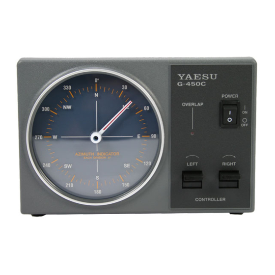
- Page 4 Controller Front/Rear Panel Controls and Switches Controller Front Panel Controller Rear Panel When replacing fuses, be sure to use a fuse of the same type and current rating.
- Page 5 Rotator Unit Components and Dimensions Rotator Unit Rotator Attachment Plate Dimensions The tower plate onto which the rotator unit is mounted must be drilled with four holes of 9 mm diameter, equally spaced on a circle of 119 mm diameter. The center-to-center distance between any two adjacent mounting holes is 84 mm.
- Page 6 The following pages describe typical antennas which are acceptable for installation with the G-450A or G-650A. The discussion below assumes maximum wind speeds of 30 meters per second (67 mph/108 kph), and it is recommended that you include a safety margin of at least 30% to account for higher wind gusts or other factors which might potentially cause damage to your installation.
- Page 7 The Wind Loading Area is within the specifications for both the G-450A and G-650A, but the net K factor (178) can only be met by the G-650A. Therefore, the above antenna system should only be mounted using a G-650A (or larger) rotator.
-
Page 8: Control Cable Installation
Control Cable Installation Before installing the rotator, mast, and antenna, prepare the rotator control cable and test rotator system performance on the ground. Potential alignment, cabling, or other problems can quickly be resolved on the ground; once a rotator is mounted, however, troubleshooting may require that the tower be climbed and/or the rotator be removed and lowered to the ground! Control Cable Preparation The control cable to be used should have six stranded conductors of at least 0.5 mm (#20 AWG) - Page 9 Assembly of 6-pin Plastic Connector Assembly of 7-pin Metal Connector Wiring for the control cable (identical numbers to be inte Pin No.7 for the metal connector is not used.
- Page 10 Mounting the Rotator and Antenna l Indoor Performance Check and Alignment 1. Temporarily connect the rotator unit and the controller using the connection cable prepared per the previous section. 2. Check to be sure that the P switch on the controller is set to O , then plug the controller’s OWER AC cable into your station’s AC outlet.
- Page 11 It is recommended that the tips of the bolts be lightly dipped in lubricating grease, to ease disassembly in the future. 2. If a thrust bearing (such as the optional Yaesu model GS-065) is to be utilized, mount it on the top of the tower (see Figure 4) using the supplied hardware.
- Page 12 Thrust Bearing GS-065 (option) Must be parallel Spring washer M8 ´ 16 (length: 16 mm) Figure 3 Figure 4 Antenna mast ´ Figure 5 Figure 6 Less than 1 m Mast Bearing GS-065 (option) Provide sufficient slack More than 1 m Rotor Figure 7 Figure 8...
- Page 13 The control cable attached to this rotator could, in the event of a nearby or direct lightning strike, carry lethal voltages down the cable and into your home. Yaesu strongly recommends the installation of suitable lightning arrestors on all control cables and coaxial lead-in cables from your antenna installation.
- Page 14 NOTE:...
- Page 15 Copyright 1998 Yaesu Musen Co., Ltd. All rights reserved. No portion of this manual may by reproduced without the permission of Yaesu Musen Co., Ltd.


