Table of Contents
Advertisement
Quick Links
"WAtCHDoG III"
Flare stack Monitoring system
Contents
1 Safety . . . . . . . . . . . . . . . . . . . . . . . . . . . . . . . . . . . . . . . 1
2 Checking the usage . . . . . . . . . . . . . . . . . . . . . . . . . . . . 2
3 Installation . . . . . . . . . . . . . . . . . . . . . . . . . . . . . . . . . . . 2
4 Commissioning. . . . . . . . . . . . . . . . . . . . . . . . . . . . . . . . 4
5 Assistance in the event of malfunction . . . . . . . . . . . . . .6
6 Technical data . . . . . . . . . . . . . . . . . . . . . . . . . . . . . . . .6
7 Certification. . . . . . . . . . . . . . . . . . . . . . . . . . . . . . . . . . .8
8 Disposal . . . . . . . . . . . . . . . . . . . . . . . . . . . . . . . . . . . . .8
oPeRAtInG InstRUCtIons
1 sAFetY
1.1 Please read and keep in a safe place
Please read through these instructions carefully before
installing or operating. Following the installation, pass the instruc-
tions on to the operator. This unit must be installed and commis-
sioned in accordance with the regulations and standards in force.
These instructions can also be found at www.docuthek.com.
1.2 explanation of symbols
1 , 2 , 3 , a , b , c = Action
➔ = Instruction
1.3 Liability
We will not be held liable for damage resulting from non-obser-
vance of the instructions and non-compliant use.
1.4 safety instructions
Information that is relevant for safety is indicated in the instructions
as follows:
DAnGeR
Indicates potentially fatal situations.
WARnInG
Indicates possible danger to life and limb.
CAUtIon
Indicates possible material damage.
All interventions may only be carried out by qualified gas techni-
cians. Electrical interventions may only be carried out by qualified
electricians.
1.5 Conversion, spare parts
All technical changes are prohibited. Only use OEM spare parts.
· Edition 01.24 · 32-00034-03 · EN
Advertisement
Table of Contents

Summary of Contents for Honeywell WATCHDOG III
-
Page 1: Table Of Contents
“WAtCHDoG III” Flare stack Monitoring system oPeRAtInG InstRUCtIons · Edition 01.24 · 32-00034-03 · EN 1 sAFetY 1.1 Please read and keep in a safe place Please read through these instructions carefully before installing or operating. Following the installation, pass the instruc- tions on to the operator. -
Page 2: Checking The Usage
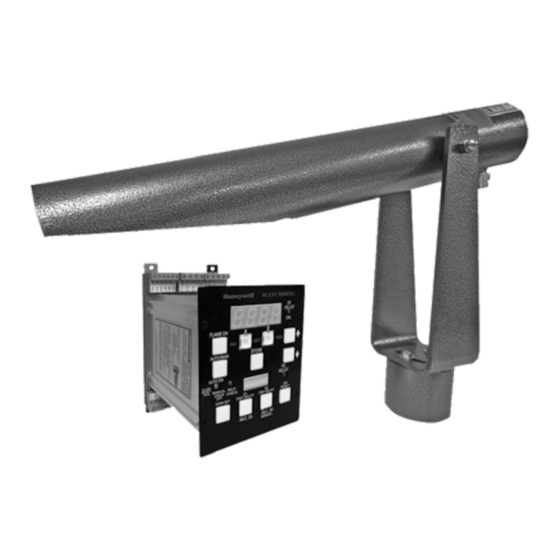
1 Connect +24VDC power to +24V IN 2 CHeCKInG tHe UsAGe 2 Connect -24VDC power to GND The “WATCHDOG III” Flame Monitoring System exists of three 3.2.1 Relay R1 and Connections components: Relay R1 will energize when flame is detected, and de- energize 1 the Model s256Be viewing head, when flame has not been detected for R1 TRIP DELAY seconds. - Page 3 Watt resistor is required. For distances greater than 1000 feet (300 LED flashing or off). The user must also select the Auto mode meters), contact your local Honeywell distributor or the factory for via the AUTO/MAN button for the signal processor to return to it guidance.
-
Page 4: Commissioning
by closing the contacts between the GND and MAN CLEAR 4 CoMMIssIonInG terminals on the signal processor. 4.1 self-Checking Function – STORE push button: When the signal processor is powered and the viewing head is - Stores new parameter values such as Flame On threshold properly connected, the self-checking function indicator SELF- and Gain. - Page 5 2 Adjust this to the desired value using the UP and DOWN arrow communicate over a single shielded twisted pair using the RS-485 buttons and press STORE. standard). The differential mode allows long wire runs in harsh ➔ (– – – –) will be displayed to indicate that the new value has environments.
-
Page 6: Assistance In The Event Of Malfunction
“S256” if the viewing head connections are correct. If the display shows “0000” the most likely cause is a 4.5 Programming for the “WAtCHDoG III” Flare stack Mon- missing source impedance matching resistor. Refer to the Viewing itoring system Head Connections section. - Page 7 Distance from pilot: Up to 1,000 ft (300 meters) line of sight Field of view: 40 ft (12 meters) Target diameter at 1,000 ft (300 meters). Cable Requirements: 4 Conductor, #22 AWG, with braided shield. Honeywell C330S cable is recommended. 6.7 Dimensions 6.7.1 s256Be viewing head dimensions 20.25" (514 mm) 1.5"...
-
Page 8: Certification
Terminals 6-13/32" (163 mm) M33514 FoR MoRe InFoRMAtIon The Honeywell Thermal Solutions family of products includes Honeywell Combustion Safety, Eclipse, Exothermics, Hauck, Kromschröder and Maxon. To learn more about our products, visit ThermalSolutions. honeywell.com or contact your Honeywell Sales Engineer.


