Table of Contents
Advertisement
Advertisement
Table of Contents
Troubleshooting

Summary of Contents for Bosch FMR-7033
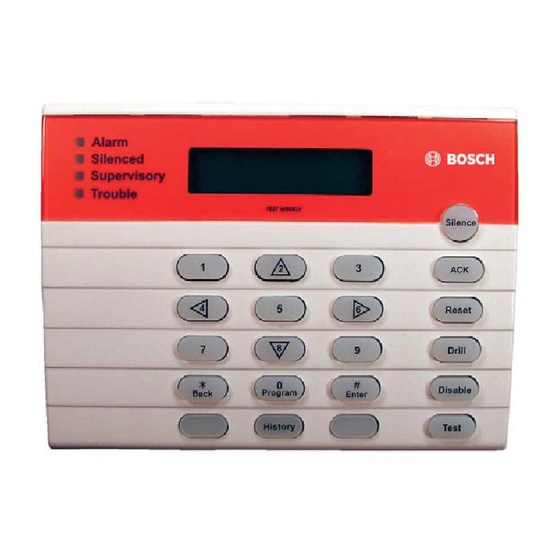
- Page 1 FMR-7033 Installation Instructions Addressable Fire System Controller...
-
Page 2: Table Of Contents
Contents ................2 Introduction ............3 Description ............3 Device Mounting ..........3 Mounting the FMR-7033 to a Surface .....3 Mounting the FMR-7033 to an Electrical Box 3 Wiring the FMR-7033 ........4 Powering the FMR-7033 .........4 Installing the FMR-7033 Instruction Label and Slide ............5 Setting the FMR-7033’s Address ....5... -
Page 3: Introduction
FPD-7024. Refer to Figure 2 on page 5 to select mounting holes. The FMR-7033 can be surface mounted, mounted to a Do not tighten the mounting screws. single or double gang box or to a four-inch square box. -
Page 4: Wiring The Fmr-7033
5.0 Powering the FMR-7033 wiring before routing. Keypad wiring cannot be shared with multiplex, option bus, The power supplied to the FMR-7033 from the R and telephone or siren wiring. B terminals on the FACP is 12 VDC with a maximum draw of 100 mA per FMR-7033 keypad. -
Page 5: Installing The Fmr-7033 Instruction Label And Slide
Installing the FMR-7033 Instruction Label and Slide For battery standby calculations, assume that the Figure 5: FMR-7033 Keypad Addresses FMR-7033 draws 75 mA from the 24 VDC battery. The FPD-7024 FACP uses a switching power supply to Address 1 Address 2... -
Page 6: Specifications
+32°F to 120°F (0°C to +49°C) Relative Humidity Width 6.25 in (15.9 cm) Height 4.6 in (11.7 cm) Depth 1.3 in (2.9 cm) Listings and Approvals UL864, FM Wiring Supervised Communication Circuit Class B, Style 4 Bosch Security Systems, Inc. | 9/08 | F01U010583-01... -
Page 7: Operating The Fmr-7033
8. Use the [Programming] key to select the programming mode. 9. Use the [History] key to view system events. 10. Use the [Enter] key to accept data when in the programming mode. Bosch Security Systems, Inc. | 9/08 | F01U010583-01... - Page 8 Bosch Security Systems, Inc. 130 Perinton Parkway Fairport, NY 14450-9199 (800) 289-0096 www.boschsecurity.com © 2008 Bosch Security Systems, Inc. F01U010583-01...


