Sign In
Upload
Manuals
Brands
ABB Manuals
Controller
ACH550-UH HVAC
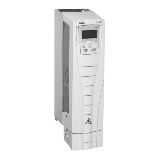
ABB ACH550-UH HVAC Frequency Drive Manuals
Manuals and User Guides for ABB ACH550-UH HVAC Frequency Drive. We have
7
ABB ACH550-UH HVAC Frequency Drive manuals available for free PDF download: User Manual, Installation, Operation & Maintenance Manual
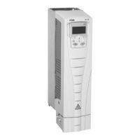
ABB ACH550-UH HVAC User Manual (642 pages)
ACH550 Series, HVAC Drives (1...550 HP), E-Clipse Bypass Drives (1...400 HP), Packaged Drives with Disconnect (1...550 HP)
Brand:
ABB
| Category:
DC Drives
| Size: 11.46 MB
Table of Contents
Table of Contents
9
Use of Warnings and Notes
7
Table of Contents
9
Installation Flow Chart
13
Preparing for Installation
14
Installing the Drive
17
HVAC Control Panel Features
37
HVAC Control Panel Modes
38
Start-Up
51
Overview
53
HVAC Default Macro
55
Supply Fan Macro
56
Return Fan Macro
57
Cooling Tower Fan Macro
58
Condenser Macro
59
Booster Pump Macro
60
Pump Alternation Macro
61
Internal Timer Macro
62
Internal Timer with Constant Speeds / PRV Macro
63
Floating Point Macro
64
Dual Setpoint with PID Macro
65
Dual Setpoint with PID and Constant Speeds
66
E-Bypass Macro
67
Hand Control Macro
68
E-Clipse Macro
69
Complete Parameter List
71
Complete Parameter Descriptions
84
Overview
189
Mechanical and Electrical Installation – EFB
191
Communication Setup – EFB
193
Activate Drive Control Functions – EFB
197
Feedback from the Drive – EFB
202
Diagnostics – EFB
204
N2 Protocol Technical Data
209
FLN Protocol Technical Data
217
Bacnet Protocol Technical Data
231
Modbus Protocol Technical Data
243
ABB Control Profiles Technical Data
251
Overview
263
Mechanical and Electrical Installation – FBA
266
Communication Setup – FBA
267
Feedback from the Drive – FBA
270
Diagnostics – FBA
271
ABB Drives Profile Technical Data
273
Generic Profile Technical Data
281
Diagnostic Displays
283
Correcting Faults
284
Correcting Alarms
290
Maintenance Intervals
293
Drive Module Fan Replacement
294
Enclosure Fan Replacement – UL Type 12 Enclosures
295
Enclosure Air Filter Replacement – UL Type 12 Enclosures
297
Capacitors
300
Ratings
301
Input Power Connections
305
ACH550-UH Drives
310
Motor Connections
313
Control Connections
319
Efficiency
322
Dimensions and Weights
324
Degrees of Protection
329
Ambient Conditions
330
Materials
331
Applicable Standards
332
Liability Limits
334
Table of Contents
352
Embedded Fieldbus
427
Overview
427
Mechanical and Electrical Installation - EFB
429
Communication Setup - EFB
431
Activate Drive Control Functions - EFB
438
Feedback from the Drive - EFB
443
Activate Bypass Control Functions - EFB
446
Feedback from the ABB E-Clipse Bypass - EFB
449
Diagnostics - EFB
450
N2 Protocol Technical Data - System
455
FLN Protocol Technical Data - System
470
Bacnet Protocol Technical Data - System
494
Modbus Protocol Technical Data - System
520
ABB Control Profiles Technical Data - Drive
528
Fieldbus Adapter
545
Overview
545
Mechanical and Electrical Installation - FBA
548
Communication Setup - FBA
549
Activate Drive Control Functions - FBA
549
Feedback from the Drive - FBA
552
Activate Bypass Control Functions - FBA
553
Feedback from the ABB E-Clipse Bypass - FBA
555
Diagnostics - FBA
556
ABB Drives Profile Technical Data
558
Generic Profile Technical Data
567
Diagnostics
569
Diagnostic Displays
569
Correcting Faults
570
Correcting Alarms
577
Bypass Status Listing
582
Error Messages
583
Technical Data
585
Input Power Connections (Supplement to ACH550-UH User's Manual)
585
Motor Connections (Supplement to ACH550-UH User's Manual)
593
E-Clipse Bypass Control Unit Connections (RBCU) (Supplement to ACH550-UH User's Manual)
594
Dimensional References
595
Dimensions and Weights (Supplement to ACH550-UH User's Manual)
599
Applicable Standards
602
ACH550-PCR/PDR Packaged Drives with Disconnect
607
Table of Contents
611
Table of Contents
613
Installation
613
Application
613
Input Disconnect Features and Functions
613
Installation Flow Chart
615
Preparing for Installation (Supplement to ACH550-UH User's Manual)
616
Installing the Wiring (Supplement to ACH550-UH User's Manual)
617
Maintenance
623
Maintenance Intervals
623
Enclosure Air Filter Replacement - UL Type / NEMA 12 Hinged Door Wall Mount Enclosures
624
Enclosure Air Filter Replacement - UL Type / NEMA 12 Floor Mount Enclosures
624
Technical Data
625
Input Power Connections (Supplement to ACH550-UH User's Manual)
625
Dimensional References
631
Dimensions and Weights (Supplement to ACH550-UH User's Manual)
634
Degrees of Protection
637
Applicable Standards
638
Advertisement
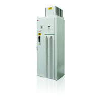
ABB ACH550-UH HVAC User Manual (307 pages)
HVAC Drives (1...550 HP)
Brand:
ABB
| Category:
Controller
| Size: 10.51 MB
Table of Contents
Safety
3
Use of Warnings and Notes
4
Safety
4
Table of Contents
5
Table of Contents
7
Installation Flow Chart
7
Preparing for Installation
8
Lifting the Drive
8
Unpack the Drive
8
Drive Identification
9
Drive Labels
9
Type Code
9
Ratings and Frame Size
9
Motor Compatibility
10
Tools Required
10
Suitable Environment and Enclosure
10
Suitable Mounting Location
11
Installing the Drive
11
Prepare the Mounting Location
11
Remove Front Cover
13
Mount the Drive
14
Wiring Overview
15
Conduit Kit
15
Wiring Requirements
15
Connection Diagrams
17
The Power and Ground Terminal Layout for Frame Sizes R5 and R6
18
Install the Wiring
19
The Power and Ground Terminal Layout for Frame Sizes R7/R8
19
Checking Motor and Motor Cable Insulation
19
R1…R6, Wiring UL Type 1 Enclosure
20
R1…R6, Wiring UL Type 12 Enclosure
21
R7…R8, Wiring (both Enclosure Types)
22
Check Installation
23
Re-Install Cover
23
Apply Input Power
25
Start-Up
26
Spin Motor
26
Motor Data
26
Edit Parameters as Appropriate
27
Macros
27
Fault and Alarm Adjustments
27
HVAC Control Panel Features
28
General Display Features
28
Soft Key Functions
28
Display Contrast
28
Start-Up
28
Start-Up by Changing the Parameters Individually
29
Start-Up by Using the Start-Up Assistant
29
Modes
31
Standard Display Mode
31
Status Information
31
Operating the Drive
32
Parameters Mode
32
Start-Up Assistant Mode
34
Changed Parameters Mode
35
Drive Parameter Backup Mode
36
Fault Logger Mode
36
Par Backup Mode
36
Download Application
38
Handling Inexact Downloads
39
Clock Set Mode
40
Download Failures
40
I/O Settings Mode
43
Application / Macro Listing
44
Application Macros
44
Control Wiring
45
Restoring Defaults
45
Selecting an Application Macro
45
HVAC Default
46
Supply Fan
47
Return Fan
48
Cooling Tower Fan
49
Condenser
50
Booster Pump
51
Pump Alternation
52
Internal Timer
53
Internal Timer with Constant Speeds / PRV
54
Floating Point
55
Dual Setpoint with PID
56
Dual Setpoint with PID and Constant Speeds
57
E-Bypass
58
Hand Control
59
Group 99: Start-Up Data
60
Parameter Descriptions
60
Group 01: Operating Data
62
Group 03: Actual Signals
66
Group 04: Fault History
70
Group 10: Start/Stop/Dir
71
Group 11: Reference Select
73
Group 12: Constant Speeds
77
Group 13: Analog Inputs
81
Group 14: Relay Outputs
82
Group 15: Analog Outputs
85
Group 16: System Controls
87
Group 17: Override
91
Changing the Override Parameters
92
Commissioning the Override Mode
92
Group 20: Limits
94
21: Start/Stop
97
Group 22: Accel/Decel
99
Group 23: Speed Control
101
Group 25: Critical Speeds
103
Group 26: Motor Control
104
Group 29: Maintenance Trig
106
Group 30: Fault Functions
107
Group 31: Automatic Reset
111
Group 32: Supervision
112
Group 33: Information
114
Group 34: Panel Display Process Variables
115
Group 35: Motor Temp Meas
118
Group 36: Timer Functions
121
Group 40: Process PID Set 1
125
PID Controller - Advanced
126
Group 41: Process PID Set 2
133
Group 42: External PID
134
Group 51: Ext Comm Module
136
Group 52: Panel Communication
137
Group 53: EFB Protocol
138
Group 81: PFA
140
Group 98: Options
152
Embedded Fieldbus
153
Overview
153
Control Interface
154
Planning
154
Mechanical and Electrical Installation – EFB
155
Communication Set-Up – EFB
156
Serial Communication Selection
156
Serial Communication Configuration
156
Activate Drive Control Functions – EFB
159
Controlling the Drive
159
Start/Stop Direction Control
159
Input Reference Select
160
Reference Scaling
160
Miscellaneous Drive Control
161
Relay Output Control
162
Analog Output Control
163
PID Control Setpoint Source
163
Communication Fault
163
Feedback from the Drive – EFB
164
Pre-Defined Feedback
164
Mailbox Read/Write
164
Actual Value Scaling
165
Diagnostics – EFB
166
Fault Queue for Drive Diagnostics
166
Serial Communication Diagnostics
166
Loss of Communication
167
Duplicate Stations/No Master Station in Line
167
Swapped Wires
167
Fault 28 – Serial 1 Err/Fault 31 – EFB1
167
Faults 31…33 – EFB1…EFB3
168
Intermittent Off-Line Occurrences
168
Modbus Protocol Technical Data - Overvew/Feature Summary
169
Modbus Addressing
170
Mapping Summary
170
Communication Profiles
170
Actual Values
176
Exception Codes
176
ABB Control Profiles Technical Data
177
ABB Drives Profile
177
DCU Profile
177
Status Word
180
State Diagram
184
Reference Scaling Table
186
ABB Drives and DCU Profiles
186
Reference Handling
188
N2 Protocol Technical Data
189
Metasys Integration
190
N2 Analog Input Objects
191
N2 Binary Input Objects
192
N2 Analog Output Objects
193
N2 Binary Output Objects
194
DDL File for NCU
194
FLN Protocol Technical Data
197
Abb Ach550
197
FLN Startup Report
197
FLN Overview Report
198
FLN Drive I/O Report
198
FLN Drive Config. Report
199
FLN Process PID Report
200
FLN External PID Report
200
Loop Gains
201
FLN Point Database
202
FLN Detailed Point Descriptions
205
Bacnet Technical Data
211
Protocol Implementation Conformance Statement (PICS) - Summary
211
Bacnet Protocol Implementation Conformance Statement
212
Bacnet Object Definitions
214
Object/Property Support Matrix
214
Binary Input Object Instance Summary
215
Binary Output Object Instance Summary
215
Binary Value Object Instance Summary
216
Analog Input Object Instance Summary
218
Analog Output Object Instance Summary
218
Analog Value Object Instance Summary
219
Bacnet Quick-Start Sequence
221
Fieldbus Adapter
223
Overview
223
Fieldbus Adapter - Control Interface
224
Fieldbus Adapter - Control Word
224
Fieldbus Adapter - Planning
225
Fieldbus Adapter - Status Word
225
Fieldbus Adapter - Reference
225
Fieldbus Adapter - Actual Values
225
Mechanical and Electrical Installation – FBA
226
Mounting Procedure
226
Communication Set-Up – FBA
227
Activate Drive Control Functions – FBA
227
System Control
228
Scaling
228
Feedback from the Drive – FBA
230
Diagnostics – FBA
231
Fault Handling
231
ABB Drives Profile Technical Data
233
ABB Drives Profile (FBA)
237
Actual Value
240
Generic Profile Technical Data
241
Diagnostics
243
Diagnostic Displays
243
Red – Faults
243
Correcting Faults
244
Flashing Green – Alarms
244
Fault Listing
244
Fault Resetting
249
Flashing Red LED
249
Red LED
249
Correcting Alarms
250
History
250
Alarm Listing
250
Maintenance Interval
253
Heatsink
253
Drive Module Fan Replacement
254
Enclosure Fan Replacement - UL Type 12 Enclosures
255
Enclosure Air Filter Replacement – UL Type 12 Enclosures
257
Frame Sizes R7/R8 – UL Type 12 Enclosure Exhaust Filters
258
Capacitors
260
Control Panel Cleaning
260
Battery
260
Technical Data
261
Ratings, 208…240 Volt Drives
261
Ratings, 380…480 Volt Drives
262
Ratings, 500…600 Volt Drives
263
Sizing
263
Symbols
263
Altitude Derating
264
Single Phase Supply Derating
264
Switching Frequency Derating
264
Temperature Derating
264
Branch Circuit Protection
265
Fuses
265
Input Power Connections
265
208…240 Volt, Fuses
266
380…480 Volt, Fuses
266
Emergency Stop Devices
267
Fuses, 500…600 Volt, Fuses
267
Input Power Cables/ Wiring
268
Ground Connections
269
Unsymmetrically Grounded Networks
269
Floating Networks
270
Drive’s Power Connection Terminals
271
Power Terminal Considerations – R6 Frame Size
271
Ring Lugs
271
Compression Lugs
272
Motor Connection Specifications
273
Motor Connections
273
Background
274
Ground Fault Protection
274
Grounding and Routing
274
Drive’s Motor Connection Terminals
275
Grounding
275
Motor Cable Requirements for CE & C-Tick Compliance
275
Motor Cable Shielding
275
Effective Motor Cable Screens
276
EN 61800-3 Compliant Motor Cables
276
Recommendation for Conductor Layout
276
Control Cables - General Recommendations
279
Control Connection Specifications
279
Analog Cables
280
Control Terminal Descriptions
280
Digital Cables
280
Drive’s Control Connection Terminals
280
Cooling Specifications
282
Efficiency
282
Dimensions and Weights
284
Heat Loss and Air Flow Data for 500…600 Volt Drives
284
Mounting Dimensions
285
Outside Dimensions – R1…R6
287
Additional Free Space Recommendations
288
Outside Dimensions – R7…R8
288
Available Enclosures
289
Degrees of Protection
289
Ambient Conditions
290
Standard Stress Testing that the ACH550 Passes
290
Material Specifications
291
Applicable Standards
292
UL Markings
292
C-Tick Marking
293
CE Marking
293
Electromagnetic Environments
293
EMC (Europe, Australia, and New Zealand)
293
Liability Limits
294
Index
295
ABB ACH550-UH HVAC User Manual (454 pages)
0.75...110 kW/1...150 HP
Brand:
ABB
| Category:
DC Drives
| Size: 6.24 MB
Table of Contents
Table of Contents
161
Data Word
171
Control Word. the Control Word Is the Principal Means for Controlling the Drive from a Fieldbus System. the Fieldbus
172
Controller Sends the Control Word to the Drive. the Drive
172
In the Control Word. Using the Control Word Requires the
172
The Drive Is in Remote (AUTO) Control
172
The Serial Communication Channel Is Defined as the Source
172
For Controlling Commands
172
Parameter 9802
294
Ext Fba
324
51 Ext
354
Switches between States According to the Bit-Coded Instructions
172
Advertisement
ABB ACH550-UH HVAC User Manual (348 pages)
HVAC Drives
Brand:
ABB
| Category:
DC Drives
| Size: 5.62 MB
Table of Contents
Table of Contents
5
Installation
9
Installation Flow Chart
9
Preparing for Installation
10
Installing the Drive
13
Control Panel
33
HVAC Control Panel Features
33
HVAC Control Panel Modes
34
Start-Up
47
Application Macros
49
Overview
49
HVAC Default Macro
51
Supply Fan Macro
52
Return Fan Macro
53
Cooling Tower Fan Macro
54
Condenser Macro
55
Booster Pump Macro
56
Pump Alternation Macro
57
Internal Timer Macro
58
Internal Timer with Constant Speeds / PRV Macro
59
Floating Point Macro
60
Dual Setpoint with PID Macro
61
Dual Setpoint with PID and Constant Speeds
62
E-Bypass Macro
63
Hand Control Macro
64
E-Clipse Macro
65
Parameters
67
Complete Parameter List
67
Complete Parameter Descriptions
80
Embedded Fieldbus
187
Overview
187
Mechanical and Electrical Installation - EFB
189
Communication Setup - EFB
191
Activate Drive Control Functions - EFB
195
Feedback from the Drive - EFB
200
Diagnostics - EFB
202
N2 Protocol Technical Data
207
FLN Protocol Technical Data
215
Bacnet Protocol Technical Data
229
Modbus Protocol Technical Data
241
ABB Control Profiles Technical Data
249
Fieldbus Adapter
261
Overview
261
Mechanical and Electrical Installation - FBA
264
Communication Setup - FBA
265
Activate Drive Control Functions - FBA
265
Feedback from the Drive - FBA
268
Diagnostics - FBA
269
ABB Drives Profile Technical Data
271
Generic Profile Technical Data
279
Diagnostic Displays
281
Correcting Faults
282
Correcting Alarms
288
Maintenance
291
Maintenance Intervals
291
Heatsink
291
Drive Module Fan Replacement
292
Enclosure Fan Replacement - UL Type 12 Enclosures
293
Enclosure Air Filter Replacement - UL Type 12 Enclosures
295
Capacitors
298
Control Panel
298
Technical Data
299
Ratings
299
Input Power Connections
303
Motor Connections
311
Control Connections
317
Efficiency
320
Cooling
320
Dimensions and Weights
322
Degrees of Protection
327
Ambient Conditions
328
Materials
329
Applicable Standards
330
Liability Limits
332
Index
334
ABB ACH550-UH HVAC User Manual (263 pages)
Brand:
ABB
| Category:
Industrial Equipment
| Size: 4.93 MB
Table of Contents
Table of Contents
7
Installation
9
Application
9
E-Clipse Bypass Features and Functions
9
Installation Flow Chart
11
Preparing for Installation (Supplement to ACH550-UH User's Manual)
12
Installing the Wiring (Supplement to ACH550-UH User's Manual)
13
Check E-Clipse Bypass Jumpers and Switches
30
Control Panel
31
Bypass Control Panel Features
31
Bypass Control Panel Modes
33
Start-Up
35
Bypass Functions Overview
39
Operating Modes
39
Relay Contact (Digital) Inputs
46
Relay Contact Outputs
48
Energy Savings Estimator
52
Application Macros
55
E-Clipse HVAC Default Macro
56
Damper Macro
57
Retrofit Macro
58
Smoke Control (Override1) Macro
59
Parameters
63
Parameter List and Descriptions
63
Embedded Fieldbus
83
Overview
83
Mechanical and Electrical Installation - EFB
85
Communication Setup - EFB
87
Activate Drive Control Functions - EFB
94
Feedback from the Drive - EFB
99
Activate Bypass Control Functions - EFB
102
Feedback from the ABB E-Clipse Bypass - EFB
105
Diagnostics - EFB
106
N2 Protocol Technical Data - System
111
FLN Protocol Technical Data - System
126
Bacnet Protocol Technical Data - System
150
Modbus Protocol Technical Data - System
176
ABB Control Profiles Technical Data - Drive
184
Fieldbus Adapter
201
Overview
201
Mechanical and Electrical Installation - FBA
204
Communication Setup - FBA
205
Activate Drive Control Functions - FBA
205
Feedback from the Drive - FBA
208
Activate Bypass Control Functions - FBA
209
Feedback from the ABB E-Clipse Bypass - FBA
211
Diagnostics - FBA
212
ABB Drives Profile Technical Data
214
Generic Profile Technical Data
223
Diagnostic Displays
225
Correcting Faults
226
Correcting Alarms
233
Bypass Status Listing
238
Error Messages
239
Technical Data
241
Input Power Connections (Supplement to ACH550-UH User's Manual)
241
Motor Connections (Supplement to ACH550-UH User's Manual)
249
E-Clipse Bypass Control Unit Connections (RBCU) (Supplement to ACH550-UH User's Manual)
250
Dimensional References
251
Dimensions and Weights (Supplement to ACH550-UH User's Manual)
255
Applicable Standards
258
ABB ACH550-UH HVAC Installation, Operation & Maintenance Manual (95 pages)
ACH550 Drives (1-550 HP); E-Clipse Bypass Drives (1-400 HP); Packaged Dr ives with Disconnect (1-500 HP)
Brand:
ABB
| Category:
Controller
| Size: 7.12 MB
Table of Contents
Safety
2
Use of Warnings and Notes
2
Contents
3
Installation
3
Unpack the Drive
4
Tools Required
4
Mounting Hardware
5
Flange Mounting Instructions
5
Prepare the Mounting Location
5
Conduit Kit
7
Connection Diagrams
8
Em3
8
Disconnecting the Internal EMC Filter
10
Ground Connections
11
Unsymmetrically Grounded Networks
11
Floating Networks
12
Checking Motor and Motor Cable Insulation
12
R1…R6, Wiring UL Type 1 Enclosure
13
R1…R6, Wiring UL Type 12 Enclosure
14
R7…R8, Wiring (both Enclosure Types)
15
Drive’s Power Connection Terminals
16
Power Terminal Considerations – R6 Frame Size
16
Drive’s Control Connection Terminals
16
Control Terminal Descriptions
16
Check Installation
18
Serial Communications
18
Before Start-Up
19
Apply Power
19
Motor Data
20
Fault and Alarm Adjustments
20
Operation
21
Control Panel Features
21
General Display Features
21
HVAC Control Panel Modes
21
Operating the Drive
22
Start-Up by Using the Start-Up Assistant
22
Start-Up by Changing the Parameters Individually
23
Diagnostics
24
Fault Listing
24
Fault History
28
Alarm Listing
29
Maintenance
31
Maintenance Intervals
32
Heatsink
32
Drive Module Fan Replacement
33
Enclosure Fan Replacement – UL Type 12 Enclosures
34
Enclosure Air Filter Replacement – UL Type 12 Enclosures
35
Frame Sizes R7/R8 – UL Type 12 Enclosure Exhaust Filters
37
Capacitors
38
Control Panel Cleaning
38
Battery
38
ACH550 E-Clipse Bypass
39
Installation – Drive
39
Installation – Bypass
39
Connection Diagrams – Vertical E-Clipse Bypass
40
Connection Diagrams – Standard E-Clipse Bypass (Wall Mounted)
41
Connection Diagrams – Standard E-Clipse Bypass (R8, Floor Mounted)
43
Power Connections – Vertical E-Clipse Bypass Configurations
44
Power Connections – Standard E-Clipse Bypass Configurations (Wall Mounted)
44
Standard Configuration (B1/B2) Diagram
45
Standard Configuration (B3) Diagram
45
UL Type 3R Configuration (B1/B2) Diagram
45
Install the Control Wiring
46
Basic Connections
47
Vertical Enclosure Terminals
48
Standard Enclosure Terminals
50
Basic Control Connections for E-Clipse HVAC Default
53
Drive Link Recovery Procedure
54
Check Installation – Bypass
54
Control Panel Settings and Checks
54
System Check: Motor Connected to ACH550 with E-Clipse Bypass
55
System Check: Motor Disconnected from the ACH550 with E-Clipse Bypass
57
Check Jumpers and Switches
59
Jumper and Switch Locations
59
DIP Switch Settings
60
E-Clipse Bypass Configurations
60
Circuit Breaker Settings
60
The Front View of the ACH550 E-Clipse Bypass Verticalconfiguration
61
The Front View of the ACH550 E-Clipse Bypass Standardconfigurations
61
Enabled LED
62
Ready (Power On) Indication
62
The Bypass Control Panel Features
62
Typical Power Diagram
62
Motor Run LED
63
Bypass Faulted LED
63
Automatic Transfer
63
Auto Indication
63
Bypass Control Panel Modes
64
Start-Up by Changing the Parameters from the Start-Up List
64
Bypass Select Key
64
Off/Reset Key
64
Start-Up by Changing the Parameters Individually from the Parameter List
65
Diagnostics - Fault Listing
66
Alarm Listing Table
72
Bypass Status Listing
76
Error Messages
77
ACH550-PCR/PDR Installation
79
ACH550-PCR/PDR - Connection Diagrams – Standard Drive with Input Disconnect (Wall Mounted)
80
ACH550-PCR/PDR - Connection Diagrams – Standard Drive with Input Disconnect (Floor Mounted)
81
Line Input Connections – Standard Drive with Input Disconnect Configurations
82
Power Connection Terminals
83
ACH550-PCR/PDR Operation
87
Input Disconnect Configuration
87
The Front View of the ACH550 Drive with Input Disconnectstandard Configurations
88
Maintenance Intervals Table
89
Enclosure Air Filter Replacement – UL Type / NEMA 12 Hinged Door Wall Mount Enclosures
89
Enclosure Air Filter Replacement – UL Type / NEMA 12 Floor Mount Enclosures
90
Complete ACH550 Drive Parameter List
91
ABB ACH550-UH HVAC User Manual (10 pages)
Brand:
ABB
| Category:
Controller
| Size: 0.22 MB
Table of Contents
Diagnostics
1
Diagnostic Displays
1
Red – Faults
1
Flashing Green – Alarms
2
Fault Listing
2
Correcting Faults
2
Fault Resetting
7
Flashing Red LED
7
History
8
Alarm Listing
8
Correcting Alarms
8
Panel Loss
9
Advertisement
Related Products
ABB ACH550-UH-04A6-2
ABB ACH550-UH-06A6-2
ABB ACH550-UH-07A5-2
ABB ACH550-UH-012A-2
ABB ACH550-UH-017A-2
ABB ACH550-UH-024A-2
ABB ACH550-UH-059A-2
ABB ACH550-UH-046A-2
ABB ACH550-UH-075A-2
ABB ACH550-UH-03A3-4
ABB Categories
Industrial Equipment
Controller
Measuring Instruments
Battery Charger
DC Drives
More ABB Manuals
Login
Sign In
OR
Sign in with Facebook
Sign in with Google
Upload manual
Upload from disk
Upload from URL