Sign In
Upload
Manuals
Brands
ABB Manuals
Measuring Instruments
AO2040
ABB AO2040 Manuals
Manuals and User Guides for ABB AO2040. We have
1
ABB AO2040 manual available for free PDF download: Operating Instructions Manual
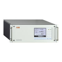
ABB AO2040 Operating Instructions Manual (362 pages)
Continuous gas analyzers Integrated analyzer system Measurement made easy
Brand:
ABB
| Category:
Measuring Instruments
| Size: 7.46 MB
Table of Contents
Table of Contents
3
Preface
9
Guideline for Installation and Commissioning
11
Safety Information
12
Intended Application
12
Special Requirements for the Operator
12
Safety Information
13
Fidas24: Information on the Safe Operation of the Gas Analyzer
15
Notes for Network and Data Security
17
Version with Type of Protection II 3G for Measurement of Non-Flammable Gases and Vapors
18
Version with Type of Protection II 3G for Measurement of Flammable Gases ('Safety Concept') and Non-Flammable Gases
20
Intended Application
20
Important Information for the Operator
21
Description
23
Internal and External Explosion Protection
24
Technical Data
25
Special Requirements for Operation
27
Limas11 IR, Uras26: Version for the 'Safety Concept
28
Caldos25, Caldos27, Magnos206: Version for the 'Safety Concept
30
Purge Gas Flow Monitoring
32
Version for Use in Class I DIV. 2 Explosion Hazard Areas
33
Preparation for Installation
34
Scope of Supply and Delivery
34
Material Required for the Installation (Not Supplied)
35
Installation Location
37
Pressure Sensor
39
Housing Purge
40
Power Supply
42
Caldos25: Preparation for Installation
44
Caldos27: Preparation for Installation
46
Fidas24: Preparation for Installation
48
Fidas24 NMHC: Preparation for Installation
51
Limas11 IR, Limas21 UV: Preparation for Installation
54
Limas21 HW: Preparation for Installation
57
Magnos206: Preparation for Installation
59
Magnos28: Preparation for Installation
61
Magnos27: Preparation for Installation
63
Uras26: Preparation for Installation
65
ZO23: Preparation for Installation
67
Oxygen Sensor: Preparation for Installation
71
Unpacking the Gas Analyzer and Installation
73
Unpacking the Gas Analyzer
73
Identification Plate
74
Analyzer Data Sheet
75
Dimensional Diagrams
76
Gas Connection Installation
78
Gas Analyzer Installation
79
Gas Line Connection
80
Caldos25: Gas Connections
80
Caldos27: Gas Connections
82
Fidas24, Fidas24 NMHC: Gas and Electrical Connections
83
Limas11 IR, Limas21 UV, Limas21 HW: Gas Connections
84
Magnos206: Gas Connections
88
Magnos28: Gas Connections
89
Magnos27: Gas Connections
91
Uras26: Gas Connections
93
ZO23: Gas Connections
95
Gas Line Connection
96
Fidas24: Connecting the Gas Lines
97
Fidas24: Connecting the Combustion Gas Line
100
Fidas24: Connecting the Sample Gas Line (Heated Sample Gas Connection)
101
Fidas24: Connecting the Sample Gas Line (Unheated Sample Gas Connection)
105
Connecting the Electrical Leads
107
Electronics Module Connection Diagram
107
Profibus Module: Electrical Connections
108
Modbus Module: Electrical Connections
109
Analog Output Module: Electrical Connections
110
Analog Input Module: Electrical Connections
111
Digital I/O Module: Electrical Connections
112
Standard Terminal Connections
114
Connecting the Signal Lines
116
System Bus Connection
118
Power Supply Line Connection - Safety Notes
121
Power Supply Line Connection to an Analyzer Module
122
Power Supply Line Connection
124
Fidas24: Power Supply Line Connection
125
Gas Analyzer Start-Up
126
Installation Check
126
Gas Path and Housing Initial Purge
127
Power Supply Activation
128
Fidas24: Gas Analyzer Start-Up
129
Limas21 HW: Gas Analyzer Start-Up
133
ZO23: Gas Analyzer Start-Up
134
Warm-Up Phase
135
Operation
136
Gas Analyzer Operation
138
Display and Control Unit
138
Screen
139
Message Display
140
Status Leds
141
Numeric Keypad
142
Cancel Keys
143
Softkeys
144
Text Entry
146
Operating by Value Entry
147
Operating by Key Entry
148
Password Protection
149
User Interface Priority
151
Access Lock
152
Menu Tree
153
Gas Analyzer Configuration: Measurement Component-Specific Functions
155
Measurement Range Configuration
155
Auto-Ranging Parameterization
161
Limit Value Monitor Parameterization
162
Filter Parameterization
163
Active Component Selection
164
Configuring a Component
165
Changing Module Name
179
Gas Analyzer Configuration: Function Blocks
180
The 'Function Blocks' Concept
180
Standard Configuration
181
The 'Function Blocks' Sub-Menu
182
Gas Analyzer Configuration: System Functions
183
Setting the Time Zone, Date and Time
183
Selecting User Interface Language
184
Changing the Password
185
Inhibit Operation
186
Setting up System Modules
187
Adding a System Module
189
Replacing a System Module
190
Removing a System Module
191
Saving the Configuration
192
Configuring Status Signals
193
Configuring an Ethernet Connection
194
Configuring a Modbus Connection
195
Configuring Profibus
196
Configuring Bus I/Os
197
Gas Analyzer Configuration: Display
198
Display Features
198
Display Overview
200
Page Overview
201
Parameter Overview
202
User Page Configuration
203
Moving a Display Element from One Page to Another
204
Moving a Display Element Within a Page
205
Configuring the Bar Display or Point Display
206
Value Entry
207
Configuring Value Entry
208
Key Entry
209
Configuring Key Entry
210
Example: Entering and Displaying the Pump Output
211
Calibration: Principles
213
Calibration Control
213
Manual Calibration
214
Automatic Calibration
216
Test Gas Supply Control for Automatic Calibration
219
Externally Controlled Calibration
222
Calibration Methods
223
Gas Analyzer Configuration: Calibration Data
225
The 'Calibration Data' Sub-Menu
225
Calibration Data for Manual Calibration
226
Calibration Data for Automatic Calibration
227
Validation
230
Calibration Data for Externally Controlled Calibration
231
Output Current Response
232
Notes for Calibrating Analyzer Modules
233
Caldos25: Notes for Calibrating
233
Caldos27: Notes for Calibrating
234
Caldos27: Single-Point Calibration with Standard Gas
235
Caldos25, Caldos27: Substitute Gas Calibration
237
Fidas24: Notes for Calibrating
238
Fidas24 NMHC: Notes for Calibrating
241
Fidas24: Substitute Gas Calibration
244
Fidas24: Response Factor and Other Relevant Variables
245
Fidas24: Conversion of Concentration Data
247
Limas11 IR, Limas21 UV, Limas21 HW: Notes for Calibrating
249
Magnos206: Notes for Calibrating
251
Magnos206: Single-Point Calibration
252
Magnos206: Substitute Gas Calibration
254
Magnos28: Notes for Calibrating
255
Magnos28: Single-Point Calibration
256
Magnos28: Substitute Gas Calibration
258
Magnos27: Notes for Calibrating
259
Magnos27: Substitute Gas Calibration
260
Uras26: Notes for Calibrating
261
ZO23: Check of the End Point and Reference Point
263
Oxygen Sensor: Notes for Calibrating
264
Calibrating the Gas Analyzer
265
Gas Analyzer Manual Calibration
265
Manual Start of the Automatic Calibration
266
Inspection and Maintenance
267
Inspection
267
Checking Gas Path Seal Integrity
268
Pump Activation, Pump Output Adjustment
269
Changing Analog Output Current Range
270
Air Pressure Correction
271
Air Pressure Value Correction
272
Calibration Reset
273
Basic Calibration
274
Cross Sensitivity Alignment
275
Carrier Gas Alignment
276
Fidas24: Standby / Restart
277
Fidas24: Replacement of the Sample Gas Filter in the Heated Sample Gas Connection
279
Fidas24: Cleaning the Air Jet Injector
281
Fidas24: Checking the Combustion Gas Supply Line for Seal Integrity
283
Fidas24: Checking the Combustion Gas Feed Path in the Gas Analyzer for Seal Integrity
285
Fidas24 NMHC: Converter Effectiveness Testing
286
Uras26: Optical Alignment
287
Uras26: Phase Alignment
290
Limas11 IR, Limas21 UV, Limas21 HW, Uras26: Measurement of Calibration Cells
291
Limas11 IR, Limas21 UV, Limas21 HW, Uras26: Relinearization
292
Limas11 IR, Limas21 UV, Limas21 HW: Thermal Link Replacement
293
Limas11 IR, Limas21 UV: Aluminum Sample Cell Cleaning
294
Limas11 IR, Limas21 UV, Limas21 HW: Quartz Sample Cell Cleaning
297
Limas11 IR, Limas21 UV: Safety Cell Cleaning
300
Limas21 UV, Limas21 HW: Lamp (EDL) Replacement
307
Limas11 IR, Limas21 UV, Limas21 HW: Amplification Optimization
310
ZO23: Function Test
312
Pneumatic Module: Disposable Filter Replacement
314
Status Messages, Troubleshooting
315
Dynamic QR Code
315
Process Status
317
System Status: Status Messages
318
System Status: Status Signals
319
Status Message Categories
320
Status Messages
322
Gas Analyzer: Troubleshooting
332
Caldos25, Caldos27, Magnos206, Magnos28, Magnos27: Troubleshooting
334
Fidas24: Troubleshooting
335
Limas11 IR, Limas21 UV, Limas21 HW: Troubleshooting
339
Uras26: Troubleshooting
340
Pneumatic Module: Troubleshooting
341
Notify Service
342
Gas Analyzer Shutdown and Packing
343
Gas Analyzer Shutdown
343
Packing the Gas Analyzer
344
Disposal
345
Analyzer Modules Operating Specifications
346
Caldos25: Operating Specifications
346
Caldos27: Operating Specifications
347
Fidas24, Fidas24 NMHC: Operating Specifications
348
Limas11 IR, Limas21 UV: Operating Specifications
349
Limas21 HW: Operating Specifications
350
Magnos206: Operating Specifications
351
Magnos28: Operating Specifications
352
Magnos27: Operating Specifications
353
Uras26: Operating Specifications
354
ZO23: Operating Specifications
355
Oxygen Sensor: Operating Specifications
356
Index
357
Advertisement
Advertisement
Related Products
ABB AO2000 Series
ABB AO2000-Fidas24
ABB AO2020
ABB AO2000-LS25
ABB Endura AZ20 series
ABB A43
ABB A44
ABB ACX
ABB ReliaGear ASPMETER A 42
ABB AW637
ABB Categories
Industrial Equipment
Controller
Measuring Instruments
Battery Charger
DC Drives
More ABB Manuals
Login
Sign In
OR
Sign in with Facebook
Sign in with Google
Upload manual
Upload from disk
Upload from URL