Sign In
Upload
Manuals
Brands
Bosch Manuals
DC Drives
rexroth KMS03.1B-A036-P-D7-ET-END-L3-TO-FW
Bosch rexroth KMS03.1B-A036-P-D7-ET-END-L3-TO-FW Manuals
Manuals and User Guides for Bosch rexroth KMS03.1B-A036-P-D7-ET-END-L3-TO-FW. We have
1
Bosch rexroth KMS03.1B-A036-P-D7-ET-END-L3-TO-FW manual available for free PDF download: Project Planning Manual
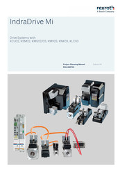
Bosch rexroth KMS03.1B-A036-P-D7-ET-END-L3-TO-FW Project Planning Manual (422 pages)
Drive Systems
Brand:
Bosch
| Category:
DC Drives
| Size: 25.35 MB
Table of Contents
Table of Contents
3
1 System Presentation
15
Introduction
15
Indradrive MI
15
Features
16
KSM02 Motor-Integrated Servo Drive
16
KMS02 Near Motor Servo Drive
17
KNK03 Mains Filter, KMV03 Supply Unit, KLC03 DC Bus Capacitor Unit, KMS03 Near Motor Servo Drive
18
Cooling Types
19
Maximum Number of Drives Per Drive Line
20
Indradrive MI Drive System
21
Components
21
Series
22
Firmware
23
System Structure
23
Overview of Functions
26
Firmware Functions (Functional Packages)
26
Type Code
27
Introduction
27
KSM02 Motor-Integrated Servo Drive
28
KSM02 Type Code
28
KMS02 Near Motor Servo Drive
31
KMS02 Type Code
31
KMS03 Near Motor Servo Drive
33
KMS03 Type Code
33
KCU02 Drive Connection Box
34
KCU02.2 Type Code
34
KMV03 Supply Unit
35
KMV03 Type Code
35
KNK03 Mains Filter
36
KNK03 Type Code
36
KLC03 DC Bus Capacitor Unit
37
KLC03 Type Code
37
Firmware
37
About this Documentation
38
Editions
38
Documentations
41
Drive Systems, System Components
41
Motors
42
Cables
42
Firmware
42
Your Comments
45
2 Important Directions for Use
47
Intended Use
47
Introduction
47
Areas of Use and Application
47
Unintended Use
48
3 Safety Instructions for Electric Drives and Controls
49
Definitions of Terms
49
General Information
50
Using the Safety Instructions and Passing Them on to Others
50
Requirements for Safe Use
50
Hazards by Improper Use
52
Instructions with Regard to Specific Dangers
52
Protection against Contact with Electrical Parts and Housings
52
Protective Extra-Low Voltage as Protection against Electric Shock
54
Protection against Dangerous Movements
54
Protection against Electromagnetic and Magnetic Fields During Operation and Mounting
55
Protection against Contact with Hot Parts
56
Protection During Handling and Mounting
56
Battery Safety
56
Protection against Pressurized Systems
57
Explanation of Signal Words and the Safety Alert Symbol
58
4 General Data and Specifications
59
Acceptance Tests and Approvals
59
Transport and Storage
61
Transporting the Components
61
Storing the Components
61
Installation Conditions
64
Ambient and Operating Conditions
64
Control Cabinet Design and Cooling
70
Mounting Position
72
Mounting Positions of Components
72
Mounting Positions of Motor-Integrated Servo Drives
73
Compatibility with Foreign Matters
73
Motor Paint
73
Voltage Testing and Insulation Resistance Testing
73
Control Voltage (24V Supply)
74
5 Technical Data of the Components
75
Explanation of Terms and Definitions
75
KSM02 Motor-Integrated Servo Drive
79
KSM02 Without Motor Holding Brake, Data Sheet
79
KSM02 with Motor Holding Brake, Data Sheet
81
KSM02 Characteristics
84
Dimensions and Technical Design
87
Dimensions
87
Technical Design
92
Bearing Load and Shaft Load
93
KMS02 Near Motor Servo Drive
95
KMS02 Data Sheet
95
KMS02 Dimensional Drawing
98
KCU02 Drive Connection Box
100
Brief Description and Use
100
KCU02 Data Sheet
101
KCU02 Dimensional Drawing
103
KMV03 Supply Unit
104
Ambient and Operating Conditions
104
Mechanics and Mounting
105
KMV03.1R-B/IXXXX Dimensional Drawing (Thermal Interface)
105
KMV03.1R-Axxxx Dimensional Drawing (Natural Convection)
106
KMV03.1R-Wxxxx Dimensional Drawing (Forced Cooling)
107
Dimensions, Mass, Insulation, Sound Pressure Level
108
Power Dissipation, Mounting Position, Cooling, Distances
109
Basic Data
110
Control Voltage
110
Mains Voltage
111
DC Bus
113
Braking Resistor
114
KLC03 DC Bus Capacitor Unit
115
KLC03 Data Sheet
115
KLC03.1N-B04M7 Dimensional Drawing (Thermal Interface)
116
KLC03.1N-A04M7 Dimensional Drawing (Natural Convection)
117
KLC03.1N-W04M7 Dimensional Drawing (Forced Cooling)
118
KNK03 Mains Filter
119
KNK03 Data Sheet
119
KNK03.1A-NR-B/IXXXX Dimensional Drawing (Thermal Interface)
120
KNK03.1A-NR-Axxxx Dimensional Drawing (Natural Convection)
121
KNK03.1A-NR-Wxxxx Dimensional Drawing (Forced Cooling)
122
KMS03 Near Motor Servo Drive
123
KMS03 Data Sheet
123
KMS03 Dimensional Drawing
126
RKH Hybrid Cable
128
RKH Hybrid Cable Incl. Communication, Technical Data
128
RKH Hybrid Cable Without Communication, Technical Data
130
Selecting RKH Hybrid Cable Incl. Communication
132
Selecting RKH Hybrid Cable Without Communication
135
Interconnection Diagrams for Ready-Made Hybrid Cables Incl. Communication
137
Kcu - Ksm/Kms
137
Ksm/Kms - Ksm/Kms
138
Flexible Cable Tracks
140
Hybrid Cable with Circular Connector
141
Has05.1-023 - Ksm/Kms
146
RHS0014 Terminal Connector
147
Interconnection Diagrams for Ready-Made Hybrid Cables Without Communication
148
Kcu - Ksm/Kms
148
Ksm/Kms - Ksm/Kms
149
Flexible Cable Tracks
151
Interconnection Diagrams for Ready-Made Hybrid Cables Used for Mains Connection
152
Knk03 - Kmv03 (Rkh0800)
152
Knk03 - Kmv03 (Rkh0801)
153
Interconnection Diagrams for Ready-Made Hybrid Cables Used for DC Bus Connection
154
Klc03 - Kmv03 (Rkh0802)
154
Klc03 - Klc03 (Rkh0803)
154
6 Connection Points
155
System Connection Points
155
Connection Point of Equipment Grounding Conductor
155
Cabinet-Bound Drive Systems
155
Cabinet Free Drive Systems
156
Ground Connection
157
KCU02 Connection Points
158
Positions of the Connection Points
158
X1, Module Bus
159
X29.1, X29.2, Multi-Ethernet
160
X49, L3 - Safe Torque off
162
Data
162
Pin Assignment, Function
162
X50, E-Stop Input
163
X52, Status Messages
164
X53, Control Voltage Output
165
X54, DC Bus, Equipment Grounding Conductor Output KSM02/KMS02
166
DC Bus Connection L+, L
167
Control Voltage Supply +24V, 0V
170
KSM02 Connection Points
172
Positions of the Connection Points
172
X37, X38, Digital Inputs/Outputs
173
X103.1, X103.2, Hybrid Cable Connection Point
177
X107, Programming Module
179
X108, X109, Communication Output Coupling
181
X118, X119, External Communication
184
X141, Safety Technology and Service Input "Release Brake
187
X141, Safety Technology "Safe Torque off
188
X141, Safety Technology "Safe Motion" (S3, SD Options)
190
X141, Without Safety Technology
191
Second Connection Point of Equipment Grounding Conductor
192
KMS02 Connection Points
194
Positions of the Connection Points
194
X37, X38, Digital Inputs/Outputs
195
X103.1, X103.2, Hybrid Cable Connection Point
195
X104, Motor Encoder Connection
196
X107, Programming Module
196
X108, X109, Communication Output Coupling
196
X118, X119, External Communication
196
X141, Safety Technology
196
X156, Motor Connection
197
X156, Motor/Motor Encoder Connection (Single-Cable Connection)
198
Second Equipment Grounding Conductor Connection Point
199
KMS03 Connection Points
200
Positions of the Connection Points
200
Motor Cable and Encoder Cable Connection
201
Condition as Supplied
201
Connection Cover: Mounting Options
202
Two-Piece Connection Cover
202
Connecting the Cables
203
XD3, Motor Connection
205
XG3, Motor Temperature Monitoring and Motor Holding Brake
206
XG4, Digital Motor Encoder Connection
209
XG8, Analog Motor Encoder Connection
210
X37, X38, Digital Inputs/Outputs
211
X103.1, X103.2, Hybrid Cable Connection Point
211
X107, Programming Module
211
X108, X109, Communication Output Coupling
211
X118, X119, External Communication
211
X141, Safety Technology
211
Second Equipment Grounding Conductor Connection Point
211
KMV03 Connection Points
212
Positions of the Connection Points
212
X37, X38, Digital Inputs/Outputs
213
X103.1, X103.2, Hybrid Cable Connection Point
213
X118, X119, External Communication
213
X141, Safety Technology (KMV03)
214
Second Equipment Grounding Conductor Connection Point
214
XD1, Mains Voltage
215
XD10, Control Voltage
216
XD13, Fan Power Supply
216
XG3, Mains Choke Temperature Contact
217
XG14, Mains Voltage Synchronization
218
XG34, Mains Contactor Control and Feedback Contacts (KNK03)
219
Connection Cover: Mounting Options
220
Two-Piece Connection Cover
220
KNK03 Connection Points
221
Positions of the Connection Points
221
Second Equipment Grounding Conductor Connection Point
221
XD1, Mains Voltage
222
XD1.2, Supply Unit
223
XD13, Fan Power Supply
223
XG14, Mains Voltage Synchronization
224
XG3, Mains Choke Temperature Contact
225
XG34, Mains Contactor Control and Feedback Contacts
226
Connection Cover: Mounting Options
227
Two-Piece Connection Cover
227
KLC03 Connection Points
228
Positions of the Connection Points
228
Second Equipment Grounding Conductor Connection Point
228
XD13, Fan Power Supply
228
X54.1, X54.2; DC Bus
229
Connection Cover: Mounting Options
230
Two-Piece Connection Cover
230
7 Notes on Project Planning
231
Combining the Individual Components
231
Power Supply
231
Sizing Mains Filters
231
Power Supply by HMV01, HMV02, HCS01, HCS02 or HCS03
231
Supply Units
231
Power Supply by HCS01
232
Power Supply by KMV03 and KNK03
232
KMV03 Supply Unit, KNK03 Mains Filter
232
Control Voltage Power Requirement 42 V
233
KCU02 Drive Connection Box
234
General Information
234
Control Voltage Supply
234
Power Supply to KSM/KMS (KCU)
236
KLC03 DC Bus Capacitor Unit
240
Application Notes
240
Hybrid Cable Length
241
Length of Hybrid Cable Incl. Communication
241
Length of Hybrid Cable Without Communication
244
Hybrid Cable Length Vs. KCU Performance
245
Hybrid Cable Length Vs. KMV03 Performance
248
Zone Setup
251
Safety Zones
251
E-Stop Function
254
Motor Fan for KSM02
256
Evaluating Motor Encoders at KMS
256
Length of Motor Cables and Encoder Cables at KMS
257
Operation with Standard Motors
257
Notes on Electrical Project Planning
259
Address Selector Switch
259
IP Configuration
260
Current Limitation
260
Motor Temperature
261
Switching Frequency
262
Notes on Mechanical Project Planning
262
Mounting Clearance
262
Output Shaft
262
Plain Shaft
262
Output Shaft with Key
262
Output Shaft with Shaft Sealing Ring
263
Bearings and Shaft Load
264
General Information
264
Radial Load, Axial Load
265
Bearing Service Life
266
Holding Brakes
267
Brake Control and Supply
267
Safety Requirements
267
Sizing Holding Brakes
268
Mechanically Attaching Driving Elements
269
General Information
269
Redundant Bearings
269
Gearbox Attachment
270
Coupling Attachment
270
Bevel Gear Pinions or Skew Bevel Driving Pinions
270
8 Identification
273
Scope of Supply
273
Kcu02
273
Ksm02/Kms02
273
Kms03
274
Kmv03
274
Knk03
274
Klc03
274
Identifying and Checking the Delivered Components
275
KSM Type Plate
275
Arrangement
275
Design
276
System Type Plate
276
KMS02 Type Plate
277
Arrangement
277
Design
278
System Type Plate
278
KMS03 Type Plate
279
Arrangement
279
Design
280
System Type Plate
280
KMV03 Type Plate
281
Arrangement
281
Design
282
System Type Plate
282
KNK03 Type Plate
283
Arrangement
283
Design
284
KLC03 Type Plate
285
Arrangement
285
Design
286
System Type Plate (Module of Configured Variants)
287
Plates at KCU02
288
Arrangement
288
Type Plate Design
288
Design of UL Performance Data Plate
289
9 Mounting and Installation
291
Introduction
291
Important Notes
291
Safety
291
Qualified Technical Staff
291
Handling the Devices
291
System Overview
292
Available Connection Points
292
Cold Plate
293
Ksm
294
Required Steps to Follow
294
Preparations for Mounting
294
Mounting KSM
294
Mechanical Interfaces
295
Flange Mounting
295
Practical Tips
295
Kms
296
Required Steps to Follow
296
Preparations for Mounting
296
Mounting KMS
296
Kcu02
297
Mounting Depths
297
Touch Guard
297
KCU02 Connection Diagram
299
Knk03, Kmv03, Klc03
300
Arranging the Devices
300
Mounting
300
Electrical Connection
300
General Information
300
Notes
301
Electrical Interfaces
302
Overall Connection Diagram
302
HMV01 Used as Supply Unit
303
HCS02 Used as Supply Unit
304
HCS03 Used as Supply Unit
305
HMV02 Used as Supply Unit
306
HCS01.1E-W0054 Used as Supply Unit
307
KMV03 Used as Supply Unit
308
Parallel Drive Lines
310
Fan Connection
311
10 Accessories
313
Overview
313
HAS01, Basic Accessory
315
HAS02, Shield Connection
316
HAS03, Control Cabinet Adapter
317
HAS05.1-018, Dummy Plate for KMS03 Encoder Connection
318
HAS05.1-019, KNK03 Mains Voltage
319
HAS05.1-020, KMV03 Control Voltage
320
HAS05.1-021, Hybrid Joint
321
Has05.1-021-Nnn-Nn
321
Has05.1-021-Ncn-Nn
322
HAS05.1-023, HCS01 Adapter
324
HAS05.1-024, Passive 42 V Supply Unit
330
View
330
Purpose
330
Properties
331
Dimensions
332
Connection
333
X37
333
X103.1, X103.2, Hybrid Cable Connection Point
333
HAS10, Mechanical Mounting Parts
334
Type Code
334
Use
335
Scope of Supply
336
RKB0021, Multi-Ethernet Cable
339
RKB0013, Multi-Ethernet Cable
340
RKB0033, Cable for Safety Technology
341
RKB0043, Communication Cable
342
RKB0044, Communication Cable
343
RKB0054, Fan Cable
344
RKS0010, Interface Cable
345
RBS0023, Connector for Safety Zone Node
346
RLS0725, KMS03 Motor Power Cable Connector
347
RGS0725, KMS03 Encoder Cable Connector
348
RHS0725, KMS03 Hybrid Motor Cable Connector
349
RH2-030DB, KMS02 - MS2N Hybrid Motor Cable
350
Metallic Flange for Circular Connectors
351
Netswitch Sercos III
352
11 Commissioning, Operation, Diagnostics and Maintenance
353
Notes on Commissioning
353
General Information
353
Preparation
353
Procedure
353
Notes on Operation
353
Diagnostic Functions
355
KMV Diagnostic Display
355
Led H14
355
KCU02 Diagnostic Display
357
KSM/KMS Diagnostic Display
359
Led H14
359
LED at Device
359
Diagnostic Display with Mpx-17/18
359
Diagnostic Display with Mpx-2X
360
Led H25 H26
361
Use
361
LED H25, Displays
362
LED H26, Displays
363
Diagnostic Messages Via Parameters
368
Firmware Functions
368
Easy Startup Mode
368
Analog Outputs
369
Oscilloscope Function
369
Patch Function
369
Monitoring Function
369
Logbook Function
369
Service Functions/Troubleshooting
370
General Information
370
Replacing Fuses F4 and F5
371
Deactivating and Dismounting the Drive
372
Deactivation
372
Dismounting
372
Replacing the Component
373
Release Holding Brake" Service Function
373
Saving Parameters
374
Firmware Update
374
Replacing the Programming Module
374
Maintenance
375
Maintenance of the Motor Component
375
General Information
375
Cleaning
375
Bearings
375
Connection Cables
375
Holding Brake - Commissioning and Maintenance Instructions
376
Maintenance of the Electronic System of the Drive
377
12 Environmental Protection and Disposal
379
Environmental Protection
379
Disposal
379
13 Service and Support
381
14 Appendix
383
Digital Inputs
383
Digital Inputs Type a (Standard)
383
Digital Inputs (Safety Technology L Options)
383
Digital Inputs (Safety Technology S Options)
384
Digital Outputs
385
Digital Outputs (Safety Technology L Options)
385
Digital Outputs (Safety Technology S Options)
386
Two-Piece Connection Cover
388
Sizing Mains Filters (Drive System)
389
Index
409
Advertisement
Advertisement
Related Products
Bosch rexroth KSM02.1B-061C-35N-M1-HP0-ET-NN-D7-NN-FW
Bosch rexroth KMM02.1B-A018-P-D7-ET-ENH-L3-TO-FW
Bosch rexroth KCU02.2N-ET-ET*-025-NN-N-NN-NW
Bosch rexroth KMV03.1R-B0007-P-D7-ET-NNNN-FW
Bosch rexroth KNK03.1A-NR-B0012-P-U226-A4-NNNN
Bosch rexroth KLC03.1N-B04M7-P-D7-NNNN
Bosch Rexroth KSM02
Bosch Rexroth KMS02
Bosch Rexroth KMS02.1B-A018
Bosch KMA 822
Bosch Categories
Dishwasher
Washer
Oven
Power Tool
Dryer
More Bosch Manuals
Login
Sign In
OR
Sign in with Facebook
Sign in with Google
Upload manual
Upload from disk
Upload from URL