Sign In
Upload
Manuals
Brands
Canon Manuals
All in One Printer
iR1200 Series
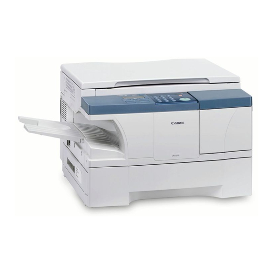
Canon iR1200 Series Manuals
Manuals and User Guides for Canon iR1200 Series. We have
3
Canon iR1200 Series manuals available for free PDF download: Service Manual, Installation Procedure
Canon iR1200 Series Service Manual (494 pages)
Brand:
Canon
| Category:
All in One Printer
| Size: 16.51 MB
Table of Contents
Table of Contents
7
Service Manual
1
Chapter 1 Introduction
15
Table of Contents
17
Product Specifications
19
Names of Parts
19
External View (Copyboard Type)
20
External View (Adf)
21
External Covers
22
Cross Section (Body)
23
Control Panel
24
Cross Section (ADF)
24
Using the Machine
24
Common Settings
29
Outline
29
User Mode Items
29
Copy Settings
34
Fax Settings*1
35
Fax Settings*1
43
Add. Registration*1
51
Timer Settings
52
Adjust./Clean
53
Print Lists
53
Count Check
54
Report Generating
54
Reports Generating (Automatically Generating Reports: if Equipped with Fax Functions)
55
Cleaning the Fixing Pressure Roller
56
Maintenance by the User
56
Outline
56
Other Cleaning
57
Storing after Unpacking the Cartridge
57
Points to Note When Handling the Cartridge
58
Cleaning the White Roller (ADF)
60
Other Cleaning
60
Safety
60
Safety of the Laser Scanner Unit
60
CDRH Requirements
61
Handling the Laser Scanner Unit
61
Safety of the Toner
62
Mechanisms/Functions
63
Product Specifications
63
Others
65
Reproduction Ratio
65
Mechanisms/Functions (ADF)
66
Mechanisms/Functions (FAX)
66
Function List
69
Printing Speed (Ab Type, a Type)
69
Chapter 2 Installation
85
Table of Contents
87
Making Pre-Checks
89
1Selecting the Site
89
Selecting the Site
89
Unpacking and Installation
90
1Before Starting
90
2Installation Procedure
90
3Unpacking
90
Before Starting
90
Installation Procedure
90
Unpacking
90
4Fitting the Cartridge
91
5Fitting the Toner Bottle
91
Fitting the Cartridge
91
Fitting the Toner Bottle
91
6Putting Paper in the Cassette
92
Putting Paper in the Cassette
92
7Putting Paper in the Manual Feed Tray
93
Interface Cable
93
Putting Paper in the Manual Feed Tray
93
9Connect the Power Cord
94
Connect the Power Cord
94
Fitting the Delivery Tray
94
Setting the Printer Functions
94
Connection to Telephone Line
95
Connecting the Modular Cable (if Equipped with Fax Functions)
95
Executing Communications Testing
95
Setting the Date/Time (User Mode)
95
Setting the Dial Type
95
Checking the Images/Operations
97
1Checking the Copy Images
97
Checking the Copy Images
97
Relocating the Machine
98
1When Relocating the Machine
98
When Relocating the Machine
98
Chapter 3 Basic Operation
101
Construction/Basic Sequence
103
Construction
105
1Functional Construction
105
Functional Construction
105
Functional Block Diagram
106
Image Processor PCB
106
4DC Controller PCB
107
DC Controller PCB
107
Analog Processor PCB
109
Control Panel PCB
109
Laser Driver/Bd PCB
109
Main Motor/Scanner Motor Driver
109
Power Supply PCB
109
Printer Controller PCB
109
Sensor PCB
109
Modular Jack PCB (if Equipped with Fax Functions)
110
NCU PCB (if Equipped with Fax Functions)
110
Sensor Relay PCB
110
Controlling the Main Motor
111
Reproduction Processes
111
Basic Sequence
115
Basic Sequence of Operations at Power-On
115
Construction/Parts Replacement Procedure
119
Construction
121
Major Components
121
Parts Replacement Procedure
122
Reader Unit
122
Removing the Rear Cover
122
Removing the Right Cover
122
Controller Pcb
123
Copyboard Glass
125
Removing the Rear Cover
125
Removing the ADF
126
Removing the Copyboard Glass
127
Removing the Sensor PCB
127
Scanner Motor
127
Removing the Copyboard Glass
128
Removing the Reader Motor Drive Unit
128
Contact Sensor
128
Removing the Contact Sensor
128
Construction
133
Construction
135
Outline
135
Laser Scanner Unit
136
Removing the Control Panel
143
Removing the Right Cover
143
Removing the Toner Supply Cover
143
Chapter 4 Original Exposure System
146
Developing Cylinder
146
Developing Blade
147
Transfer Charging Roller
149
Toner Bottle Sensor
150
Waste Toner Full Sensor
152
Chapter 5 Laser Exposure
146
Chapter 6 Image Formation
146
Detecting Jams
159
Delivery Jams
159
Jam Detection Outline
159
Stationary Jams
159
Door Open Jam
160
Other Jams
160
Cassette Pick-Up Unit
161
1Outline
161
2Retry Pickup
161
3Detecting the Size of Paper
162
Manual Feed Pickup Unit
163
1Outline
163
2Retry Pickup
163
3Detecting the Size of Paper
164
Delivery
165
1Outline
165
2Auto Delivery Control
165
3Reducing the Copying Speed
166
Parts Replacement Procedure
167
Pickup Roller
167
Cassette Pickup Solenoid
168
Removing the
168
Separation Pad
168
Pickup Solenoid
169
Manual Feed (Upper)
170
Manual Feed (Lower)
171
Manual Pickup Roller
171
Manual Feed Tray Sensor
172
Removing the Cartridge Cover
174
Removing the Upper Cover
174
Motor Unit
176
Manual Feed Pickup Solenoid
177
Registration Roller Unit
183
Vertical Path Roller
184
Chapter 7 Pickup/Feeding System
159
Chapter 8 Fixing System
187
Table of Contents
189
Construction
191
1Outline
191
Outline
191
Various Control Mechanisms
192
Controlling the Fixing Roller Temperature
192
Controlling the Fixing Temperature
192
Controlling the Fixing File Bias Temperature
193
Controlling the Fixing Film Bias
193
Protective Functions
194
1Outline
194
2Detecting a Fault in the Fixing Assembly
194
Outline
194
Parts Replacement Procedure
196
Fixing Unit
196
Removing the Delivery Cover
196
Removing the Delivery Rear Cover
196
Removing the Delivery Upper Cover
196
Removing the Control Panel
197
Removing the Fixing Assembly
197
Pressure Roller
198
Removing the Delivery Cover
198
Disconnect Connector
199
Removing the Control Panel
199
Removing the Delivery Rear Cover
199
Removing the Delivery Upper Cover
199
Removing the Fixing Assembly
200
Removing the Fixing Film Unit
201
Fixing Film
202
Removing the Delivery Cover
202
Removing the Delivery Upper Cover
202
Removing the Fixing Pressure Roller
202
Disconnect Connector
203
Removing the Control Panel
203
Removing the Delivery Rear Cover
203
Removing the Fixing Assembly
204
Fixing Delivery Sensor
205
Removing the Fixing Film Unit
205
Removing the Delivery Cover
206
Chapter 9 External And Controls
209
Fans/Power Supply System
211
Fans
214
1Outline
214
Outline
214
Power Supply System
215
Power Supply
215
Route of Low Voltage Power Supply
215
Hegh-Voltage Power Supply Circuit
216
Backup Battery
217
Lithium Battery (BAT1)
217
Outline
217
Protection Function
217
Protective Functions
217
Vanadium Lithium Secondary Battery (BAT2)
218
Types of Data
219
Printing the Backup Data List
220
Energy-Saving Function
221
Outline
221
Operation
222
Analog Processor Pcb
223
Removing the Analog Processor PCB
224
Removing the DC Controller PCB
225
Removing the Right Cover
225
Removing the Delivery Cover
226
Image Processor PCB
229
Removing the Image Processor PCB
229
Removing the Printer Controller PCB
229
Ncu Pcb
230
Printer Controller PCB
230
Removing the NCU PCB (if Equipped with Fax Functions)
230
Modular Jack PCB
231
Removing the Modular Jack PCB
231
Supply Pcb
231
Relay Pcb
236
Cartridge Cover
241
Toner Supply Cover Switch
243
Removing the Image Processor PCB
252
Removing the Main Motor Unit
253
Right Door
254
Removing the Manual Feed Tray (Lower)
254
Removing the Right Door
255
Table of Contents
260
Chapter 10 Original Feeding System
261
Basic Construcion
261
Basic Operation
262
Picking up and Moving Originals
262
Detection Jams
264
Types of Jams
264
Adf Drive Unit
267
Adf Motor Unit
269
Drive Unit
271
Separation Roller Unit
274
Separation Roller
277
Original Separation Pad
284
Registration Roller
285
White Roller
288
Feed Roller
290
Removing the Delivery Stacking Tray
298
Original Sensor
299
Removing the Original Delivery Roller
299
Removing the ADF Motor Unit
301
Registration Sensor
302
Original Delivery Sensor
304
Removing the ADF Motor Unit
304
Removing the Original Delivery Sensor
306
Mounting the Slide Guide (Front, Rear)
307
Removing the Slide Guide (Front, Rear)
307
Slide Guide
307
Delivery Stacking Tray
308
Cleaning
313
Chapter 11 Maintenance and Inspection
315
Periodically Replaced Parts
315
Durables
316
Durables and Consumables
316
Scheduled Servicing Basic Procedure
317
Scheduled Servicing Chart
317
Cleaning
318
Outline
318
Selfoc Lens Array of the Contact Sensor
318
Cassette Pickup Roller
319
Fixing Inlet Guide
319
Manual Feed Pickup Roller
319
Paper Path
319
Separation Pad
319
Separation Static Eliminator
319
Transfer Charging Roller
319
Transfer Guide
319
Back of Copyboard Glass (Back of Shading Plate)
320
Delivery Roller
320
Fixing Pressure Roller
320
Original Pickup Roller (ADF)
320
Original Separation Pad (ADF)
320
Original Separation Roller (ADF)
320
ADF Registration Roller (ADF)
321
Copyboard Glass (Original Reading Area) (ADF)
321
Original Delivery Roller (ADF)
321
Original Feed Roller (ADF)
321
Table of Contents
325
Chapter 12 Standards and Adjustments
327
Image Adjustments
327
Leading Edge Read Start Position Adjustment
327
Left/Right Edge Read Start Position Adjustment
327
Scanning System
329
Preparing a Test Sheet for Adjustment
329
Fixing System
330
Nip Adjustment
330
Electrical Components
331
Outline
331
Adf
332
Outline
332
Auto Adjustment
333
Registration Adjustment
333
Original Read Position Adjustment
334
Trailing Edge Read End Position Adjustment
335
Table of Contents
339
Chapter 13 Correcting Faulty Images
341
Making Lnitial Checks
341
Checking the Drum Unit
341
Checking the Paper
341
Making Initial Checks
341
Others
341
Site Environment
341
Troubleshooting Flow Chart
342
Checking the Photointerrupters
343
Making Checks in Response to an Image Fault
343
Adf
346
Body
346
Clutch/Solenoid
346
Outline
341
Outline of Electrical Components
346
Body
347
Sensor
347
Adf
348
Lamps, Heaters, and Others
349
Others
349
Pcbs
350
Error Code Table/Fax Error Codes
355
Error Code Table
357
Troubleshooting Malfunctions (Service Error)
357
Fax Error Codes
362
User Error Code
365
Causes and Remedies for User Error Codes
365
Service Error Code
372
Causes and Remedies for Service Error Codes
372
Control Board
381
Common Faults
404
Outline
407
Outline
409
Chapter 14 Self Diagnosis
411
Chapter 15 Service Mode
411
Using Service Mode
411
List of Menus
412
Service Mode Table
420
Bit Switch Settings
420
Menu Switch Settings
432
Numeric Parameter Setting
434
Ncu Setting
438
Special Setting
438
Country/Region of Installation
439
ISDN Setting
439
Setting the Original Reading Functions
439
Setting the Printer Parameters
440
Counter
443
Pdl
443
Downloading
445
Generating a Report
445
Clearing
446
ROM Indication
446
Resetting the Contact Sensor Position
447
Service Mode Default Setting
447
Test Mode
463
Service Report
480
System Dump List
481
Chapter 16 Service Tools
491
List of Special Tools
491
List of Solvents and Oils
492
Advertisement
Canon iR1200 Series Service Manual (424 pages)
Brand:
Canon
| Category:
Printer
| Size: 4.25 MB
Table of Contents
Table of Contents
7
Chapter 1 Product Outline
17
Specifications
19
Type
19
Mechanisms
19
Functions
20
Others
22
Reproduction Ratio
23
Copying Speed (AB Type, a Type)
24
ADF (if Equipped with ADF Functions)
26
FAX (if Equipped Fax Functions)
27
Communications Specifications
27
Printer Section Specifications
28
Scanner Section Specifications
28
Functions
29
Names of Parts
33
External View
33
Body (ADF Type)
33
Body (Copyboard Type)
34
Chapter 2 Using the Machine
47
Control Panel
49
User Mode
53
User Report
66
Manually Generating a Report
66
Automatically Generating Reports (if Equipped with Fax Functions)
67
Memory Clear List
68
Service Mode
69
Outline
69
Using Service Mode
71
List of Service Mode Menus
72
Bit Switch Settings (#1 SSSW)
80
Menu Switch Settings (#2 MENU)
96
Numeric Parameter Setting (#3 NUMERIC Param.)
98
SPECIAL Setting (#4A SPECIAL)
103
NCU Setting (#4B NCU)
103
ISDN Setting (#4C ISDN)
103
Country/Region of Installation (#5 TYPE)
103
Setting the Original Reading Functions (#6 SCANNER)
104
Setting the Printer Parameters (#7 PRINTER)
105
SSSW Setting
105
NUMERIC Param
107
Print Count
107
Print Reset
107
Mlt Cleaning
107
Pdl (#8 Pdl)
107
Counter (#9 COUNTER)
108
Counter
108
Clearing the Counter Readings
109
Generating a Report (#10 REPORT)
109
Downloading (#11 DOWNLOAD)
109
Clearing (#12 CLEAR)
110
ROM Indication (#13 ROM)
110
Resetting the Contact Sensor Position (#14 CS SET)
110
Service Mode Default Setting
111
Test Mode (TEST MODE)
121
Outline
121
List of Test Mode Items
122
D-RAM Test (1: D-RAM)
129
CCD Test (2: CCD TEST)
130
PRINT Test (3: PRINT)
131
MODEM NCU Test (4: MODEM NCU)
132
Relay Test
132
Frequency Test
133
G3 Signal Transmission Test
135
(6: Faculty Test)
136
AGING Test
136
Reception Test
136
Test
136
Service Report
143
Manually Generating Reports
143
System (Service) Data List
143
System Dump List
144
Key History Report
146
Automatically Generated Reports
148
Print Spec Report
148
Error TX Report (for Service)
149
RX Report (for Service)
150
Chapter 3 Installation
157
Fitting the Cartridge
157
Fitting the Toner Bottle
158
Putting Paper in the Cassette
160
Putting Paper in the Manual Feed Tray
161
Connecting the Interface Cable
162
Connecting the Modular Cable (if Equipped with Fax Functions)
162
Connecting the Power Cord
163
Fitting the Delivery Tray
163
Checking the Copy Images
163
Setting the Printer Functions
164
Chapter 4 Operation
169
Basic Operation
171
Reproduction Processes
171
Outline
171
Functional Construction
174
Outline of the Electrical Circuitry
175
Functional Block Diagram
175
Outlines of Functions
176
DC Controller PCB
177
Image Processor PCB
177
Control Panel PCB
178
Power Supply PCB
178
Analog Processor PCB
179
Laser Driver/Bd PCB
179
Main Motor/Scanner Motor Driver
179
Printer Controller PCB
179
Sensor PCB
179
Modular Jack PCB (if Equipped with Fax Functions)
180
NCU PCB (if Equipped with Fax Functions)
180
Sensor Relay PCB
180
Power-On Sequence
181
Controlling the Main Motor
182
Outline
183
Image Reading/Processing System
183
Outline
184
Laser Exposure System
184
Outline
186
Image Formation System
186
Outline
187
Pickup/Feeding/Delivery System
187
Outline
188
Pickup from the Cassette
188
Detecting the Size of Paper
189
Outline
190
Pickup from the Manual Feed Tray
190
Detecting the Size of Paper
191
Operation
191
Retry Pickup
191
Auto Delivery Control
192
Outline
192
Outline
193
Outline
194
Types of Jams
194
Operation
195
Controlling the Fixing Temperature
197
Controlling the Fixing Film Bias
199
Detecting a Fault in the Fixing Assembly
199
Fixing Heater Safety Mechanism
199
Power Supply System
201
Low Voltage Circuit
201
Low Voltage Power Supply Circuit
201
Protective Functions
203
High-Voltage Power Supply Circuit
203
Controlling the ESS Mechanism
203
Operation
203
Outline
203
Others
204
Fan
204
Outline
204
Back-Up Batteries
205
Back-Up Function
205
Outline
211
Chapter 5 Mechanical System
215
Points to Note When Disassembling/Assembling the Machine
217
Disassembly
220
Externals/Auxiliary System
220
External Covers
220
Removing the Left Cover/Rear Cover
221
Removing the Right Cover
221
Cover
222
Removing the Toner Supply Cover
222
Rear Cover
224
Removing the Cartridge
224
Removing the Upper Cover
225
Removing the Right Door
227
Removing the Humidity Sensor
236
Removing the Toner Bottle Sensor
237
Removing the Waste Toner Full Sensor
237
Pcbs
238
Removing the Image Processor PCB
238
Removing the Analog Processor PCB
239
Removing the Sensor PCB
241
Removing the DC Controller Pcb/Power Supply PCB
242
Removing the Printer Controller PCB
246
Removing the NCU PCB
247
Removing the Modular Jack PCB
247
Removing the Sensor Relay PCB
247
Original Reading/Processing System
248
Removing the Contact Sensor
248
Removing the Reader Motor Drive Unit
249
Removing the Reader Unit
251
Laser Exposure System
253
Removing the Laser Scanner Unit
253
Image Formation System
255
Removing the Transfer Charging Roller
255
Removing the Developing Cylinder/Developing Blade
256
Notes on Replacing the Developing Cylinder/Developing Blade
259
Pickup/Feeding System
260
Removing the Cassette Pickup Roller
260
Removing the Cassette Pickup Solenoid
262
Removing the Manual Feed Tray (Upper)
264
Removing the Manual Feed Tray (Lower)
264
Removing the Manual Feed Pickup Roller
265
Removing the Separation Pad
266
Removing the Manual Feed Pickup Solenoid/Manual Feed Tray Paper Sensor
266
Removing the Vertical Path Roller
267
Removing the Registration Roller Unit
270
Fixing System
271
Removing the Fixing Assembly
271
Removing the Fixing Film Unit/Fixing Pressure Roller
273
Removing the Delivery Sensor
274
ADF System (if Equipped with ADF Functions)
275
Externals/Auxiliary Control System
275
Removing the ADF
275
Removing the ADF Drive Unit
277
Removing the ADF Motor Unit
278
Removing the Slide Guide (Front, Rear)
279
Mounting the Slide Guide (Front, Rear)
280
Pickup System
281
Removing the Separation Roller Unit
281
Removing the Original Pickup Roller/Original Separation Roller
283
Removing the Original Sensor/Registration Sensor
283
Removing the Original Separation Pad
284
Removing the ADF Registration Roller
285
Feeding System
287
Removing the White Roller
287
Removing the Feeding Outside Guide
288
Removing the Feed Roll
289
Removing the Original Feed Roller
290
Delivery System
291
Removing the Delivery Stacking Tray/Original Delivery Roller
291
Removing the Original Delivery Sensor
292
Chapter 6 Maintenance and Inspection
293
Periodically Replaced Parts
295
Durables
295
Scheduled Servicing Chart
295
Cleaning
296
Cleaning by the User (Machine)
296
Cleaning the Fixing Pressure Roller
296
Other Cleaning
296
Cleaning by the User (ADF)
297
Cleaning the White Roller6-3
297
Other Cleaning
297
Cleaning at Time of a Service Visit (Machine)
298
Selfoc Lens Array of the Contact Sensor
298
Cassette Pickup Roller
299
Manual Feed Pickup Roller
299
Registration Roller
299
Separation Pad
299
Chapter 7 Troubleshooting
303
Standards and Adjustments
305
Checking the Pressure (Nip) of the Fixing Pressure Roller
305
Making Adjustments
307
Making Adjustments When Replacing Major Parts
307
Preparing a Test Sheet for Adjustment
308
Adjusting the Electrical Systems
309
Adjusting the Mechanical Systems
309
Contact Sensor LED Intensity Auto Adjustment
309
Leading Edge Read Start Position Adjustment
310
Left/Right Edge Read
311
Start Position Adjustment
311
Making Adjustments (ADF)
312
Preparing a Test Sheet for Adjustment
312
Adjusting the Mechanical Systems
313
Left/Right Registration Adjustment
314
Adjusting the Electrical Systems
316
Original Read Position Adjustment
316
Registration Arch Auto Adjustment
316
Original Speed Adjustment
317
Leading Edge Read Start Position Adjustment
318
Trailing Edge Read End Position Adjustment
319
When Replacing a Component
320
When Replacing the Image Processor PCB
320
After Finishing the Work7-17
321
Troubleshooting
322
Making Initial Checks
322
Checking the Drum Unit
322
Checking the Paper
322
Others
322
Site Environment
322
Troubleshooting Flow Chart
323
Making Checks in Response to an Image Fault
324
Checking the Originals against the Symptom
324
Copyboard Glass and White Sheet
324
Troubleshooting Image Faults
325
Troubleshooting Procedure for Image Faults
325
The Output Is too Light
326
The Output Is too Dark
329
The Output Has Fuzzy, Black Vertical Lines
330
The Output Is Foggy Vertically
330
The Output Has Fuzzy, Black Horizontal Lines
331
The Output Is Foggy Horizontally
331
The Output Has Black Lines (Horizontal)
332
The Output Has Black Lines (Vertical)
332
The Output Has White Lines (Vertical)
332
The Output Has White Spots (Vertical)
332
The Output Has White Lines (Horizontal)
333
The Output Has White Spots (Horizontal)
333
The Output Is Soiled
334
The Back of the Output Is Soiled
335
The Output Has a Fixing Fault
336
The Output Has a Blurry Image
337
The Output Has Left/Right Displacement
337
The Output Has Poor Sharpness (out of Focus)
338
The Output Is Blank
339
The Output Is Solid Black
341
Troubleshooting Malfunctions
342
Troubleshooting Malfunctions (Service Error)
342
Troubleshooting Malfunctions (Other than Service Error)
346
Power Is Absent
346
The LCD Fails to Operate
346
The Contact Sensor Fails to Move
347
The Contact Sensor LED Fails to Go on
347
The Message "CHECK TONER/DRUM CRG" Fails to Go off
348
The Speaker Fails to Generate Sound
348
The Message "SUPPLY REC
349
The Message "REC. PAPER JAM SLIDE PLATEN LEFT" Fails to Go off
350
COVER" Fails to Go off
351
The Message "PLATEN/COVER
351
Troubleshooting Malfunctions (if Equipped with ADF Functions)
352
Original Pickup Fails
352
Troubleshooting Malfunctions (Printer Functions)
353
Printing Fails to Start
353
Printing Stops in the Middle
353
Troubleshooting (Faults Unique to Models Equipped with Fax Functions)
355
Troubleshooting Communication Faults
355
Service Error Code Output
357
Error Codes
357
Equalizer: No.05 of Service Soft Switch #2 MENU
357
T0 Timer: No.10 of Service Soft Switch #3 NUMERIC Param
357
Transmission Level (ATT): No.07 of Service Soft Switch #2 MENU
357
Transmission Page Timer: SW12 of Service Soft Switch #1 SSSW
357
Echo Protect Tone: SW03 Bit
358
Echo Remedy
358
Number of Final Flag Sequences: SW04 Bit 2 of Service Soft Switch #1 SSSW
358
RTN Signal Transmission Condition: No. 02, 03, and 04 of Service Soft Switch #3 NUMERIC Param
358
Sssw
358
T1 Timer: No.11 of Service Soft Switch #3 NUMERIC Param
358
Password
359
Signals
359
Subaddress
359
Timer
360
How to Record the Protocol
361
Causes and Remedies for User Error Codes
362
Causes and Remedies for Service Error Codes
367
Common Faults
389
Troubleshooting Feeding Faults
390
Outline
390
Paper Jams
391
Pickup Assembly (Cassette)
391
Pickup Assembly (Manual Feed Tray)
393
Feeding Assembly
395
Fixing Delivery Assembly
397
Checking the Rotation of the Cassette Pickup Roller and the Vertical Path Roller
398
Checking the Rotation of the Registration Roller and the Gear for the Photosensitive Drum
398
Checking the Rotation of the Rollers and Gears
398
Original Jams (if Equipped with ADF Functions)
399
Feeding Faults
400
Double Feeding
400
Wrinkles
401
Faulty Feeding of Originals (if Equipped with ADF Functions)
402
Double Feeding
402
Skew
402
Arrangement of the Electrical Parts
403
Checking the Photointerrupters
403
Arrangement and Functions of Electrical Components
405
Body
405
Solenoids, Motors, Fans
405
ADF (if Equipped with ADF Functions)
406
Sensors
407
ADF (if Equipped with ADF Functions)
408
Others
410
Pcbs
412
Variable Resistors, Light Emitting Diodes (LED), and Check Pins by PCB
413
Image Processor PCB
413
DC Controller PCB
414
List of Special Tools
421
Appendix
422
List of Solvents and Oils
422
Canon iR1200 Series Installation Procedure (24 pages)
Brand:
Canon
| Category:
Printer Accessories
| Size: 0.61 MB
Table of Contents
Table of Contents
7
Making Pre-Checks
10
1Selecting the Site
10
Unpacking and Installation
11
1Before Starting
11
2Installation Procedure
11
3Unpacking
11
4Fitting the Cartridge
12
5Fitting the Toner Bottle
12
6Putting Paper in the Cassette
13
7Putting Paper in the Manual Feed Tray
14
8Connecting the Interface Cable
14
9Connect the Power Cord
15
10Fitting the Delivery Tray
15
11Setting the Printer Functions
15
Connection to Telephone Line
16
1Connecting the Modular Cable (if Equipped with Fax Functions)
16
2Setting the Date/Time (User Mode)
16
3Setting the Dial Type
16
4Executing Communications Testing
16
Checking the Images/Operations
18
1Checking the Copy Images
18
第 2 章 Relocating the Machine
19
When Relocating the Machine
20
Advertisement
Advertisement
Related Products
Canon SmartBase iR1200s
Canon iR1600 Series
Canon iR1022F
Canon iR1022iF
Canon iR1570F
Canon iR1024 Series
Canon iR1025 Series
Canon iR1019 Series
Canon imagerunner ir1133
Canon iR1024J
Canon Categories
Printer
Digital Camera
All in One Printer
Camcorder
Scanner
More Canon Manuals
Login
Sign In
OR
Sign in with Facebook
Sign in with Google
Upload manual
Upload from disk
Upload from URL