Sign In
Upload
Manuals
Brands
Canon Manuals
Copier
NP7160
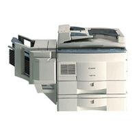
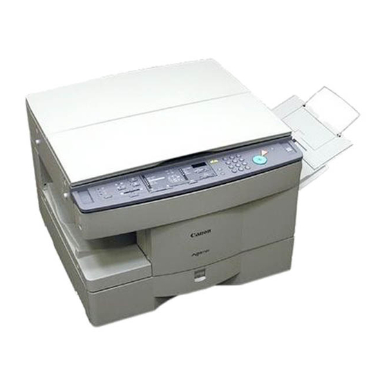
Canon NP7160 Manuals
Manuals and User Guides for Canon NP7160. We have
2
Canon NP7160 manuals available for free PDF download: Service Manual
Canon NP7160 Service Manual (395 pages)
Brand:
Canon
| Category:
Copier
| Size: 10.07 MB
Table of Contents
Introduction
3
System Configuration
5
Contents
7
Features
17
Specifications
18
Copier
18
Type
18
Mechanisms
18
Performance
19
Cassette Feeding Module - C1
24
Names of Parts
25
External View
25
Cassette Feeding Module
26
Cross Section
27
Operating the Machine
29
Control Panel
29
User Mode
31
Outline
31
Routine Maintenance (by the User)
34
Points by Note (by the User)
35
Image Formation
36
Static Latent Image Formation Block
37
Basic Operation
41
Basic Mechanisms
41
Functional Construction
41
Outline of the Electrical Circuitry
42
Basic Sequence of Operations at Power-On
44
Basic Sequence of Operations at Copy Start
46
Main Motor (M1) Control Circuitry
48
Operation
48
Detecting an Error
48
Inputs to the DC Controller
49
Outputs from the DC Controller
52
Inputs to and Outputs from Accessories
56
Exposure System
59
Outline of Operation
59
Changing the Reproduction Ratio
59
Lens Drive System
61
Driving the Lens
61
Motor Control Circuit
62
DC Controller PCB
62
Moving the Lens
63
Scanner Drive System
64
Scanner Motor Control Circuit
65
Relationship between Scanner Sensor and Signals
65
Basic Sequence of Operations (Scanner)
66
Scanner Movement in Page Separation Mode
67
Detecting the Original Size
68
Detection of the Original Size by the ADF
68
Document Size Detection by Document Sensor (NP7210 Only)
69
Document Size
72
Disassembly/Assembly
73
Scanner Drive Assembly
74
Removing the Scanner Motor
74
Removing the Scanner Drive Cable
75
Routing the Scanner Drive Cable
77
Adjusting the Position of the Mirror
78
Adjusting the Tension of the Scanner Drive Cable
79
Lens Drive Assembly
80
Removing the Lens Drive Motor
80
Removing the Mirror Motor
81
Image Formation System
85
Outline of the Processes
85
Basic Sequence of Operations (Image Formation System)
86
NP7161/NP7160 (A4, 2 Copies)
86
NP7210 (A4, 2 Copies)
86
Controlling the Intensity of the Scanning Lamp
87
Protection Mechanisms
89
Controlling the Primary/Transfer Bias
90
Controlling the Developing/Separation Static Eliminator Bias
91
Turning On/Off the Developing DC Bias
92
Turning On/Off the Developing AC Bias/Separation Eliminator Bias
93
Controlling the Developing DC Bias to a Specific Voltage to Suit Copy Density
94
Controlling the Blank Exposure Lamp
96
Turning on the Blank Exposure Lamp in Reduce Mode
97
Turning on the Blank Exposure Lamp in Direct/Enlarge Mode
97
Turning on the Blank Exposure Lamp in Multifeeder Mode
97
Developing Assembly/Drum Cleaner
98
Detecting and Controlling the Level of Toner
100
Monitoring the Waste Toner Feeding Screw
101
Monitoring the Waste Toner Box
102
Control by the Cleaner Thermistor
104
Copying Speed down Sequence
104
Auto Density Adjustment (AE)
105
Measuring the Density of the Original
105
Scanning Lamp Assembly
108
Removing the Scanning Lamp
108
Mounting the Scanning Lamp
109
Removing the Thermal Fuse
109
Exposure Assembly
110
Removing the Pre-Exposure/Blank Exposure Lamp Assembly
110
Removing the Dust-Proofing Glass
110
Cleaning the no 6 Mirror
111
Drum Unit
112
Removing the Drum Unit
112
Cleaning the Photosensitive Drum
113
Removing the Cleaner Thermistor
113
Primary Charging Assembly
114
Removing the Primary Charging
114
Transfer Charging Assembly
115
Removing the Transfer Charging Assembly
115
Charging Wire
116
Stringing the Charging Wires
116
Adjust the Height of the Charging Wires
120
Developing Assembly
121
Removing the Developing Assembly
121
Removing the Developing Blade
121
Removing the Developing Cylinder
122
Pick-Up/Feeding System
127
Pick-Up from the Cassette
128
Pick-Up Operation
128
Sequence of Operations (Pick-Up/Feeding)
129
NP7210 Vertical Path Paper Control (A4, 2 Sheets)
130
Operation of the Cassette Lifter
131
Detecting the Size of the Cassette
133
Detecting the Cassette Size
134
Pick-Up from the Multifeeder
135
Detecting the Size of Paper in the Multifeeder
136
Sequence of Operation (Pick-Up from Multifeeder)
137
Controlling the Registration Clutch
138
Sequence of Operations (Jam Detection)
140
Registration Delay Jam
140
Registration Stationary Jam
140
Delivery Delay Jam
141
Delivery Stationary Jam
141
Pick-Up Assembly
143
Removing the Pick-Up Roller
143
Mounting the Pick-Up Roller
143
Removing the Pick-Up Drive Assembly
144
Removing the Pick-Up Assembly
144
Removing the Feed Roller
145
Removing the Separation Roller
145
Mounting the Separation Roller
146
Multifeeder Asseembly
147
Removing the Multifeeder Tray
147
Removing the Multifeeder Assembly
147
Removing the Multifeeder Pick-Up Roller
148
Removing the Separation Pad
148
Adjusting the Pressure of the Separation Pad
149
Removing the Registration Roller Assembly
150
Cassette Assembly
151
Removing the Cassette Size Switch
151
Changing the Cassette Size (AB/INCH)
152
Adjusting the Left/Right Registration
153
Fixing System
157
Controlling the Fixing Temperature
158
Copy Speed Reducing Sequence (NP7210 Only)
161
Error Detection Circuit
164
Surface Temperature of the Fixing Upper Roller
165
Activation of the Fixing Heater (H1)
165
Fixing Assembly
169
Construction
169
Locking Mechanism
169
Removing the Fixing Assembly
169
Removing the Fixing Heater
171
Removing the Thermal Switch Assembly
172
Removing the Main Thermistor
173
Removing the Sub Thermistor
173
Removing the Fixing Upper Roller
174
Removing the Fixing Lower Roller
175
Removing the Heat Discharge Roller
175
Adjusting the Height of the Fixing Inlet Guide
175
Adjusting the Nip
176
Measuring the Nip
176
Delivery Assembly
177
Removing the Upper Separation Claw
177
Removing the Lower Separation Claw
177
Removing the Delivery Roller
178
Removing the Upper Left Cover
191
Removing the Delivery Lower Cover
191
Removing the Delivery Upper Cover
191
Removing the Lower Inside Cover
192
Control Panl
193
Removing the Control Panel
193
Copyboaed Glass
194
Removing the Copyboard Glass
194
Fans
195
Removing the Scanner Cooling Fan
195
Removing the Exhaust Fan
196
Remove the Ozone Filter
197
Counter Assembly
198
Main Motor Assembly
198
Removing the Counter Assembly
198
Removing the Main Motor Assembly
198
Removing the DC Controller PCB
199
Points to Note When Replacing the DC Controller PCB
199
Removing the Power Supply PCB
200
Removing the High-Voltage Power Supply PCB
200
Lamp Regulator PCB
201
Removing the Lamp Regulator PCB
201
Inputs to and Outputs from Cassette Relay PCB
205
Cassette Feeding
206
Cassette Motor Control Circuit
207
Pick-Up/Feeding Sequence
208
Vertical Path Paper Control of NP7161 and NP7160
209
Vertical Path Paper Control of NP7210
210
Waste Toner Swing Control
211
Jam Detection
212
Jam Detection Sequence
213
External Cover
215
Removing the Upper Front Cover
215
Drive Assembly
216
Removing the Cassette Motor
216
Removing the Pick-Up Rollers
217
Installing the Pick-Up Rollers
217
Removing the Feed Rollers
219
Removing the Separation Rollers
219
Installing the Separation Rollers
220
Cassette Size Switch Assembly
221
Cassette Relay PCB
223
Removing the Cassette Relay PCB
223
Installation
227
Selecting the Site
227
Unpacking and Installation
228
Removing the Metal Fixings
229
Mounting the Drum Unit
230
Cleaning the Parts and Making Checks
232
Checking the Images/Operations and User Mode
234
Supplying Toner
236
Relocating the Machine
238
Installing the Control Card IV N
239
Installing the Remote Diagnostic Device II
240
Installing the Accessory Counter
249
Procedure for Installing the Accessory Heater
251
Installing the Heater Switch
251
Installing the Cassette/Drum Heater
253
Installing the Mirror Heater
255
Installing the Cassette Heater
256
Maintenance and Service
261
Periodically Replaced Parts
261
Consumables and Durables
262
Scheduled Servicing Chart
264
Scheduled Servicing Table
266
Guide to Troubleshooting Tables
271
Standards and Adjustments
275
Mechanical
275
Leading Edge Non-Image Width (Blank Exposure Lamp off Timing)
275
Image Leading Edge Margin (Registration on Timing)
275
Left/Right Registration (Cassette)
276
Routing the Scanner Drive Cble
277
Adjusting the Height of the Charging Wires
283
Adjusting the Height of the Fixing Assembly Inlet Guide
286
Adjusting the Pressure of the Lower Roller
286
Electrical System
288
Obtaining Optimum Exposure
288
AE Adjustment
289
After Replacing the DC Controller PCB
292
Checking the Photointerrupters
293
Image Faults
297
Initial Checks
297
Checking the Site Environment
297
Checking the Originals
297
Checking the Charging Assembly
298
Checking the Developing Assembly
298
Checking the Paper
298
Checking the Periodically Replaced Parts
298
Troubleshooting Image Faults
301
The Copy Is too Light (Halftone Area Only)
301
The Copy Has Uneven Density (Front Side Dark)
303
The Copy Has Uneven Density (Front Side Light)
303
The Copy Is Foggy (Overall)
304
The Copy Is Foggy (Vertical)
305
The Copy Has Black Lines (Vertical, Fuzzy, Thick)
305
The Copy Has Black Lines (Vertical, Thin)
305
The Copy Has White Spots (Vertical)
306
The Copy Has White Lines (Vertical)
306
The Back of the Copy Is Soiled
308
The Copy Has Faulty Fixing
309
The Copy Has a Displaced Leading Edge
310
The Copy Has a Blurred Image
311
The Copy Is Foggy (Horizontally)
311
The Copy Has Poor Sharpness
312
The Copy Is Blank
313
The Copy Is Solid Black
313
Troubleshooting Malfunctions
314
E000
314
E001
315
E002/E003
316
E004
317
E010
317
E013
317
E030
318
E031
318
E202 (the Keys on the Control Panel Fail to Operate)
318
E208
319
E210
319
E220
319
E261
320
E710/E711
320
E712
320
E717
320
E800
321
E805
321
E821
321
AC Power Is Absent
322
DC Power Supply Is Absent
323
The Scanner Fails to Move
324
The Lens Fails to Move
325
The Mirror Fails to Move
325
The Scanning Lamp Fails to Turn on
326
The Pre-Exposure Lamp Fails to Turn on
327
The Blank Exposure Lamp Fails to Turn on
327
Pick-Up Fails (Cassette)
328
Pick-Up Operation Fails (Multifeeder)
329
The Registration Roller Fails to Rotate
329
The Fixing Heater Fails to Mturn on
330
The Add Toner Indicator Does Not Flash/Turn on
330
The Add Toner Indicator Fails to Turn off
331
The Waste Toner Box Full Indicator Fails to Flash/Turn on
331
The Waste Toner Box Full Indicator Fails to Turn off
332
The Add Paper Indicator Fails to Flash
332
The Add Paper Indicator Fails to Turn off
333
The Jam Indicator Fails to Flash
333
The Jam Indicator Fails to Turn off
334
The Set Control Card Indicator Fails to Turn on
334
The Set Control Card Indicator Fails to Turn off
334
E904
335
Fails to Pick up
336
Load Paper Indicator Fails to Flash
337
Load Paper Indicator Fails to Extinguish
337
Troubleshooting Feeding Problems
338
Copy Jams
338
Pick-Up /Feeding Assembly
339
Fixing/Delivery Assembly
340
Faulty Feeding
341
Double Feeding
341
Wrinkles
341
Arrangement and Functions of Electrical Parts
342
Motors, Fans,Clutches and Solenoids
344
Heater, Lamps and Others
346
Pcbs
348
Variable Resistors, Light-Emitting Diodes and Check Pins by PCB
350
Power Supply PCB
353
High-Voltage Power Supply PCB
354
Service Mode
355
Using Service Mode
355
Starting Service Mode
355
Selecting Service Mode
355
Using Adjust Mode and Function Mode
356
Display Mode
357
Guide to Jam Types and Jam History
358
Guide to ADF Jam History and ADF Jam Type
359
Guide to ADF Warning
359
Guide to Sorter Jam History and Sorter Jam Type
359
Guide to Sorter Tray Warning
360
Checking the Control Panel Keys
360
How to Read no 127 Document Size Indicator (NP7210 Only)
361
I/O Display Mode
362
Guide to Nos 202, 203, 204, 205, 219, 220, 221, 222 and 223
363
Adjust Mode
366
Function Mode
368
Option Mode
369
Paper Sizes Available under no 505/506
371
Counter Mode
372
Application Mode
373
Self Diagnosis
374
Adf
378
Sorter
379
Special Tools List
391
Solvents and Oils
392
Advertisement
Canon NP7160 Service Manual (346 pages)
Brand:
Canon
| Category:
Printer
| Size: 2.66 MB
Table of Contents
Table of Contents
9
System Configuration
7
General Description
17
Chapter 1 General Description
19
Features
19
Specifications
20
Copier
20
Mechanisms
20
Type
20
Performance
21
Others
23
Names of Parts
26
External View
26
Cross Section
27
Copier
27
Operating the Machine
28
Control Panel
28
User Mode
30
Routine Maintenance (by the User)
32
VII.image Formation
34
Outline
34
Chapter 2 Basic Operation
37
Basic Operation
37
Basic Mechanisms
39
Functional Construction
39
Outline of the Electrical Circuitry
40
Power-On
41
Basic Sequence of Operations at
42
Basic Sequence of Operations
42
Basic Sequence of Operations at Copy Start
44
Main Motor (M1) Control Circuitry
46
Detecting an Error
46
Operation
46
Outline
46
Inputs to the DC Controller
47
Inputs to the DC Controller (3/3)
49
Outputs from the DC Controller
50
Outputs from the DC Controller (1/4)
50
Outputs from the DC Controller (2/4)
51
Chapter 3 Exposure System
55
Outline of Operation
57
Changing the Reproduction Ratio
57
Lens Drive System
59
Driving the Lens
59
Outline
59
Motor Control Circuit
60
Moving the Lens
61
Scanner Drive System
62
Outline
62
Scanner Motor Control Circuit
63
Relationship between Scanner Sensor and Signals
63
Basic Sequence of Operations (Scanner)
64
Scanner Movement in Page Separation Mode
65
Others
66
Detecting the Original Size
66
Detection of the Original Size by the ADF
66
Disassembly/Assembly
67
Scanner Drive Assembly
68
Removing the Scanner Drive Cable
69
Routing the Scanner Drive Cable
71
Adjusting the Position of the Mirror
72
Adjusting the Tension of the Scanner Drive Cable
73
Lens Drive Assembly
74
Removing the Lens Drive Motor
74
Chapter 4 Image Formation System
77
Image Formation System
77
Outline of the Processes
79
Outline
79
Basic Sequence of Operations (Image Formation System)
80
Controlling the Intensity of the Scanning Lamp
81
Outline
81
Operation
82
Protection Mechanisms
83
Controlling the Primary/Transfer Bias
84
Outline
84
Turning On/Off the Primary/Transfer Bias
84
Controlling the Developing/Separation Static Eliminator Bias
85
Outline
85
Turning On/Off the Developing
86
Turning On/Off the Developing DC Bias
86
AC Bias/Separation Eliminator Bias
87
Controlling the Developing
88
Controlling the Blank Exposure Lamp
90
Outline
90
Turning on the Blank Exposure Lamp in Direct/Enlarge Mode
91
Turning on the Blank Exposure Lamp in Reduce Mode
91
Motor
92
Outline
92
Developing Assembly/Drum Cleaner Assembly
92
Detecting and Controlling the Level of Toner
94
Monitoring the Waste Toner Feeding Screw
95
Monitoring the Waste Toner Box
96
Control by the Cleaner Thermistor
98
Copying Speed down Sequence
98
Auto Density Adjustment (AE)
99
Measuring the Density of the Original
99
Outline
99
Disassembly/Assembly
101
Scanning Lamp Assembly
102
Removing the Scanning Lamp
102
Mounting the Scanning Lamp
103
Removing the Thermal Fuse
103
Exposure Assembly
104
Removing the Dust-Proofing Glass
104
Removing the Pre-Exposure/Blank Exposure Lamp Assembly
104
Cleaning the No. 6 Mirror
105
Drum Unit
106
Removing the Drum Unit
106
Cleaning the Photosensitive Drum
107
Removing the Cleaner Thermistor
107
Primary Charging Assembly
108
Removing the Primary Charging Assembly
108
Transfer Charging Assembly
109
Removing the Transfer Charging Assembly
109
Charging Wire
110
Stringing the Charging Wires
110
Adjusting the Height of the Charging Wires
114
Developing Assembly
115
Removing the Developing Blade
115
Removing the Developing Cylinder
116
Chapter 5 Pick-Up/Feeding System
119
Outline of Operation
121
Pick-Up from the Cassette
122
Pick-Up Operation
122
Sequence of Operations (Pick-Up/Feeding)
123
Operation of the Cassette Lifter
124
Detecting the Size of the Cassette
126
Outline
126
Detecting the Cassette Size
127
Pick-Up from the Multifeeder
128
Pick-Up Operation
128
Detecting the Size of Paper in the Multifeeder
129
Sequence of Operations (Pick-Up from Multifeeder)
130
Controlling the Registration Clutch
131
Detecting Jams
132
Outline
132
Sequence of Operations (Jam Detection)
133
Registration Delay Jam
133
Registration Stationary Jam
133
Delivery Delay Jam
134
Delivery Stationary Jam
134
Disassembly/Assembly
135
Pick-Up Assembly
136
Removing the Pick-Up Roller
136
Assembly
137
Removing the Pick-Up Drive
137
Assembly
140
Multifeeder Assembly
140
Removing the Multifeeder Tray
140
Removing the Multifeeder Assembly
140
Removing the Multifeeder
140
Removing the Separation Pad
141
Adjusting the Pressure of the Separation Pad
142
Registration Roller Assembly
143
Removing the Registration Roller Assembly
143
Cassette Assembly
144
Removing the Cassette Size Switch
144
Changing the Cassette Size (AB/INCH)
145
Adjusting the Left/Right Registration
146
Chapter 6 Fixing System
147
Fixing System
147
Outline of Operation
149
Outline
149
Controlling the Fixing Temperature
150
Error Detection Circuit
153
Outline
153
Activation of the Fixing Heater (H1)
154
Surface Temperature of the Fixing Upper Roller
154
Disassembly/Assembly
155
Fixing Assembly
156
Construction
156
Locking Mechanism
156
Removing the Fixing Assembly
156
Removing the Fixing Heater
158
Assembly
159
Removing the Thermal Switch
159
Removing the Main Thermistor
160
Removing the Sub Thermistor
160
Removing the Fixing Upper Roller
161
Adjusting the Height of the Fixing Inlet Guide
162
Removing the Fixing Lower Roller
162
Removing the Heat Discharge Roller
162
Adjusting the Nip
163
Delivery Assembly
164
Removing the Lower Separation Claw
164
Removing the Upper Separation Claw
164
Removing the Delivery Roller
165
Chapter 7 Externals/Auxiliary Mechanisms
167
Fans
169
Power Supply
172
Outline of Power Supply
172
Power Supply Circuitry
173
AC Power Supply
173
DC Power Supply
173
ADF and Sorter
174
Mirror Heater, Cassette/Drum Heater, and Accessory Cassette Heater
174
Protection Mechanisms of the Power Supply Circuitry
175
Disassembly/Assembly
176
External Covers
177
Removing the Right Door
178
Removing the Upper Right Cover
178
Inside Cover
179
Removing the Delivery Lower Cover
179
Removing the Delivery Upper Cover
179
Removing the Upper Left Cover
179
Removing the Lower Inside Cover
180
Control Panel
181
Removing the Control Panel
181
Copyboard Glass
182
Removing the Scanner
183
Fans
183
Removing the Counter Assembly
186
Main Motor Assembly
186
Removing the Main Motor Assembly
186
Counter Assembly
186
DC Controller PCB
187
Removing the DC Controller PCB
187
Points to Note When Replacing
187
The DC Controller PCB
187
Removing the High-Voltage Power Supply PCB
188
Removing the High-Voltage
188
Removing the Power Supply PCB
188
Power Supply PCB
188
Lamp Regulator PCB
189
Removing the Lamp Regulator PCB
189
Chapter 8 Installation
191
Selecting the Site
193
Unpacking and Installation
194
Unpacking
194
Removing the Metal Fixings
195
Mounting the Drum Unit
196
Cleaning the Parts and Making Checks
198
Checking the Images/Operations and User Mode
200
Supplying Toner
202
Relocating the Machine
204
IV. Installing the Control Card IV N
205
Installing the Remote Diagnostic Device II
206
Installing the Accessory Counter
215
VII.installing the Accessory Heater
217
Installing the Heater Switch
217
Mounting the Cassette/Drum Heater
218
Installing the Mirror Heater
219
Chapter 9 Maintenance and Servicing
221
Periodically Replaced Parts
223
Copier
223
Consumables and Durables
224
Copier
224
Scheduled Servicing Chart
225
Scheduled Servicing Table
227
Copier
227
Chapter 10 Troubleshooting
229
Guide to Troubleshooting Tables
231
Image Adjustment Basic Procedure
233
Points to Note for Scheduled Servicing
234
Standards and Adjustments
235
Mechanical
235
Image Leading Edge Margin (Registration on Timing)
235
Leading Edge Non-Image Width (Blank Exposure Lamp off Timing)
235
Width (Blank Exposure Lamp off Timing)
235
Left/Right Registration (Cassette)
236
Exposure System
237
Routing the Scanner Drive Cable
237
Adjusting the Position of the Mirror
238
Adjusting the Tension of the Scanner Drive Cable
239
Image Formation System
240
Outline
240
Stringing the Charging Wires
240
Adjusting the Height of the Charging Wires
243
Pick-Up/Feeding System
244
Adjusting the Pressure of the Separation Pad
244
Changing the Cassette Size
244
Adjusting the Height of the
246
Adjusting the Pressure of the Lower Roller (Nip)
246
Fixing System
246
Electrical System
248
Obtaining Optimum Exposure
248
AE Adjustment
249
After Replacing the DC Controller PCB
252
Checking the Photointerrupters
253
Image Faults
255
Initial Checks
255
Checking the Copyboard Cover and Copyboard Glass
255
Checking the Originals
255
Checking the Site Environment
255
Checking the Charging Assembly
256
Checking the Developing Assembly
256
Checking the Paper
256
Checking the Periodically Replaced Parts
256
Others
256
Image Fault Samples
258
Troubleshooting Image Faults
259
The Copy Is too Light
259
Troubleshooting
259
The Copy Is too Light
260
The Copy Has Uneven Density
261
The Copy Is Foggy. (Overall)
262
The Copy Has Black Lines
263
The Copy Is Foggy. (Vertical)
263
The Copy Has White Lines
264
The Copy Has White Spots
264
The Copy Has White Spots
265
The Back of the Copy Is Soiled
266
The Copy Has Faulty Fixing
267
Leading Edge
268
The Copy Has a Displaced Leading Edge
268
The Copy Has a Blurred Image
269
The Copy Is Foggy
269
The Copy Has Poor Sharpness
270
The Copy Is Blank
271
The Copy Is Solid Black
271
Troubleshooting Malfunctions
272
IV. Troubleshooting Malfunctions
272
Copier
272
E000
272
E001
273
E002/E003
274
E004
275
E010
275
E013
276
E030
276
E031
277
E202 (the Keys on the Control Panel Fail to Operate.)
277
E208
278
E210
278
E220
279
E261
279
E710/E711
279
E712
280
E717
280
E800
281
E805
281
E821
281
AC Power Is Absent
282
DC Power Supply Is Absent
283
The Scanner Fails to Move
284
The Lens Fails to Move
285
The Mirror Fails to Move
285
The Scanning Lamp Fails to Turn on
286
The Blank Exposure Lamp Fails to Turn on
287
The Pre-Exposure Lamp Fails to Turn on
287
Pick-Up Fails. (Cassette)
288
Pick-Up Operation Fails
289
The Registration Roller Fails to Rotate
289
The Add Toner Indicator Does Not Flash/Turn on
290
The Fixing Heater Fails to Turn on
290
The Add Toner Indicator Fails to Turn off
291
The Waste Toner Box Full Indicator Fails to Flash/Turn on
291
The Add Paper Indicator Fails to Flash
292
The Waste Toner Box Full Indicator Fails to Turn off
292
The Add Paper Indicator Fails to Turn off
293
The Jam Indicator Fails to Flash
293
The Jam Indicator Fails to Turn off
294
The Set Control Card Indicator Fails to Turn on
294
The Set Control Card Indicator Fails to Turn off
295
Troubleshooting Feeding Problems
296
Copy Jams
296
Pick-Up/Feeding Assembly
297
Fixing/Delivery Assembly
298
Faulty Feeding
299
Double Feeding
299
Wrinkles
299
Arrangement and Functions of Electrical Parts
300
Sensors and Switches
300
Motors, Fans, Clutches, and Solenoids
302
Heaters, Lamps, and Others
304
Pcbs
306
Variable Resistors, Light-Emitting Diodes, and Check Pins by PCB
307
DC Controller PCB
307
Lamp Regulator PCB
310
Power Supply PCB
310
High-Voltage Power Supply PCB
311
Service Mode
312
Outline
312
Using Service Mode
312
Selecting Service Mode
312
Starting Service Mode
312
Using Adjust Mode and Function Mode
313
Display Mode [1]
314
I/O Display Mode [2]
318
F. Adjust Mode [3]
322
Function Mode [4]
324
Option Mode [5]
325
Counter Mode [6]
327
Application Mode [7]
328
Self Diagnosis
329
A. Copier
329
B. Adf
333
Sorter
334
Cassette Feeding Module
334
Appendix
335
Special Tools List
343
Solvents and Oils
344
Advertisement
Related Products
Canon NP7161
Canon NP7210
Canon NP-70
Canon NP-2020
Canon NP-2120
Canon NP6016
Canon NP6012
Canon NP-1010
Canon NP-1015
Canon NP-1215S
Canon Categories
Printer
Digital Camera
All in One Printer
Camcorder
Scanner
More Canon Manuals
Login
Sign In
OR
Sign in with Facebook
Sign in with Google
Upload manual
Upload from disk
Upload from URL