Sign In
Upload
Manuals
Brands
Cisco Manuals
Network Router
WS-X4515 - Supervisor Engine IV
Cisco WS-X4515 - Supervisor Engine IV Manuals
Manuals and User Guides for Cisco WS-X4515 - Supervisor Engine IV. We have
1
Cisco WS-X4515 - Supervisor Engine IV manual available for free PDF download: Hardware Installation And Maintenance Manual
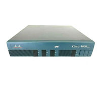
Cisco WS-X4515 - Supervisor Engine IV Hardware Installation And Maintenance Manual (143 pages)
4000 Series
Brand:
Cisco
| Category:
Network Router
| Size: 2.63 MB
Table of Contents
Table of Contents
5
Figure 2-38 E1 Interface Cable for 120-Ohm, Balanced Connections (with Twinax Connectors)
12
Figure 2-39 E1 Interface Cable for 120-Ohm, Balanced Connections (with RJ-45 Connector)
12
About this Manual
15
Audience
15
Document Objectives
15
Document Organization
15
Document Conventions
16
Chapter 1 Cisco 4000 Series Overview
19
External Differences in Models of the Cisco 4000 Series
19
Figure 1-1 Cisco 4000 Series Chassis-Front Panel
20
Series Specifications
20
Memory Systems
22
Chapter 2 Preparing for Installation
23
Safety Recommendations
24
Safety with Electricity
24
Preventing Electrostatic Discharge Damage
25
General Site Requirements
25
Site Environment
25
Site Configuration Precautions
26
Installation Checklist
27
Required Tools and Equipment
28
Site Log
28
Preparing to Make Connections
29
Slot Numbering
29
Unit Numbering
29
Figure 2-3 Router-Rear View Showing Serial Port Unit Numbering
30
Figure 2-4 Slot Filler Panel
31
Network Connection Considerations
32
Ethernet Connections
32
Token Ring Connections
35
Serial Connections
37
Console Port and Auxiliary Port Connection Considerations
31
Auxiliary Port Connections
31
Console Port Connections
31
Figure 2-13 EIA/TIA-232 Adapter Cable Connectors, Network End
38
Figure 2-22 Dual Serial Network Processor Module Jumpers, J4 and J5-NRZI Setting
43
Figure 2-25 Single-Mode FDDI Network Interface Connectors, FC Type
48
Figure 2-26 Multimode FDDI Network Interface Connector, MIC Type
48
Figure 2-32 Channelized T1 Network Interface Processor
53
Channelized E1 Connections
54
Figure 2-35 Location of Jumpers on the CE1 Module
55
Figure 2-36 E1 Interface Cable for 75-Ohm, Unbalanced Connections (with BNC Connectors)
55
ATM Connections
56
Figure 2-37 E1 Interface Cable for 120-Ohm, Balanced Connections (with DB-15 Connectors)
56
Inspecting the System
58
BRI Connections
51
Channelized T1 Connections
52
Figure 2-14 EIA/TIA-449 Adapter Cable Connectors, Network End
38
Figure 2-19 Four-Port Serial Port Adapter Cables
41
Figure 2-23 Router Serial Cable Connections
43
Fiber Distributed Data Interface Connections
47
Chapter 3 Installing the Router
59
Making Console Port Connections
59
Rack-Mount and Wall-Mount Procedures Overview
59
Figure 3-1 Making Token Ring Connections
60
Figure 3-4 60-Pin Four-Port Serial Cable Connections
62
Figure 3-9 Creepage and Clearance Distances between BRI Module and Components
68
Making FDDI Network Connections
69
Making T1 Connections
72
Making E1 Connections
74
Making ATM Connections
75
Connecting Routers with a DC-Input Power Supply
77
Wiring the DC-Input Power Supply
78
Making Final Connections to the Router
80
Making Serial Connections
62
Making BRI Connections
64
Making Network Connections
60
Making Token Ring Connections
60
Making Ethernet Connections
61
Chapter 4 Troubleshooting the Initial Hardware Configuration
81
Problem Solving
81
Troubleshooting the Power and Cooling Systems
82
Troubleshooting the Network Processor Modules and Cables
82
Environmental Reporting Features
83
Reading Front-Panel LED Indicators
83
System LED Operation
83
Figure 4-2 Dual-Port Ethernet Network Processor Module Leds
84
Figure 4-13 Eight-Port BRI Network Processor Module
91
Figure 4-15 Channelized T1 Network Interface Processor
92
Figure 4-16 Channelized E1 Network Interface Processor
93
ATM Network Processor Module LED Indicators
94
Figure 4-3 Single-Port Ethernet Network Processor Module Leds
84
CE1 Network Processor Module LED Indicators
93
Reading Network Processor Module LED Indicators
84
Ethernet Network Processor Module LED Indicators
84
Figure 4-4 Token Ring Module Network Connector
85
Figure 4-7 Serial Port Labeled V2
87
Figure 4-10 Dual-Attachment Single-Mode FDDI Module-End View
89
BRI Network Processor Module LED Indicators
91
Figure 4-14 Four-Port BRI Network Processor Module
91
CT1 Network Processor Module LED Indicators
92
FDDI Network Processor Module LED Indicators
89
Token Ring Network Processor Module LED Indicators
85
Four Port Serial Module Indicators
86
Dual Serial Network Processor Module LED Indicators
87
Chapter 5 Maintaining and Upgrading the Router
95
Accessing the Router Internal Components
95
Removing the Component Tray
96
Figure 5-1 Component Tray Removal for Chassis with a Safety Latch
97
Figure 5-3 Typical Cisco 4000 Series Component Tray-Cisco 4000-M Shown
99
Figure 5-5 Cisco 4000-M SIMM Locations
101
Replacing Main Memory Simms
102
Removing Main Memory SIMMS
103
Side View
104
Top View
104
Installing Main Memory Simms
105
Figure 5-9 Installing Main Memory Simms
106
Replacing Shared-Memory Simms
107
Inserting Shared-Memory Simms
108
Memory Replacement Procedures
100
Removing Network Processor Modules
98
Figure 5-10 Inserting Shared-Memory Simms
109
Figure 5-12 Inserting Flash-Memory Simms
112
Figure 5-13 Boot Roms Locations
113
Replacing Boot Roms in the Cisco 4000-M
113
Replacing Network Processor Modules
114
Replacing the Component Tray
114
Testing Your Installation
114
Cable Specifications
115
Figure 5-11 Removing the Boot Helper Flash Memory SIMM
110
Removing the Cisco 4500-M and Cisco 4700 Boot Helper Flash Memory SIMM
110
Installing Flash-Memory Simms
111
Table B-1 Virtual Configuration Bit Meanings
117
Changing Configuration Register Settings
118
Configuring the Boot Field
119
Appendix A Cabling Specifications A-1
117
Appendix B Cisco 4000 Series Virtual Configuration Register
117
Virtual Configuration Register Settings
117
Table B-2 Explanation of Boot Field (Configuration Register Bits 00-03
119
Table B-3 Default Boot Filenames
120
Table B-4 Configuration Register Settings for Broadcast Address Destination
121
Table B-5 System Console Terminal Baud Rate Settings
121
Enabling Booting from Flash Memory
122
Appendix C Cisco 4000-M ROM Monitor
123
Available ROM Monitor Commands
124
Entering the Cisco 4000-M ROM Monitor Program
125
Table C-1 O Command Options
125
Appendix D Cisco 4500-M and Cisco 4700 ROM Monitor
127
Entering the ROM Monitor Program
127
Available ROM Monitor Commands
128
ROM Monitor Command Conventions
128
Debugging Commands
130
Configuration Register
130
Appendix E Operating Conditions for the United Kingdom
133
For United Kingdom Use Only
133
Appendix F Operating Conditions for the European Community
135
Advertisement
Advertisement
Related Products
Cisco WS-X4582
Cisco WS-X4548-GB-RJ45-RF - Line Card Expansion Module
Cisco WS-X45-SUP6-E - Supervisor Engine 6-E
Cisco WS-X4516-10GE - Supervisor Engine V-10GE
Cisco WS-X4516-10GE-RF - Catalyst 4500 Series Supervisor Engine V-10GE
Cisco WS-X4606-X2-E - Line Card Expansion Module
Cisco WS-X4904-10GEeql - 10GE Card
Cisco WS-X4248-FE-SFP - Line Card Switch
Cisco WS-X4424 - Catalyst 4000 Series 10/100/1000 BASE-T Copper Gigabit Ethernet Module
Cisco WS-X401310GE-RF - Supervisor Engine II-Plus-10GE
Cisco Categories
Switch
IP Phone
Network Router
Wireless Access Point
Network Hardware
More Cisco Manuals
Login
Sign In
OR
Sign in with Facebook
Sign in with Google
Upload manual
Upload from disk
Upload from URL