Sign In
Upload
Manuals
Brands
Fujitsu Manuals
Storage
M2488
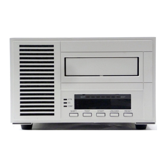
Fujitsu M2488 Manuals
Manuals and User Guides for Fujitsu M2488. We have
3
Fujitsu M2488 manuals available for free PDF download: Product Manual, User Manual, Instruction Manual
Fujitsu M2488 Product Manual (528 pages)
Brand:
Fujitsu
| Category:
Storage
| Size: 4.71 MB
Table of Contents
Preface
3
Table of Contents
5
Information Locator
6
Table of Contents
6
List of Figures
17
List of Tables
27
Installation Instructions
27
Introduction
27
Preparing the M2488 and Its Optional Equipment
27
Configurations
27
Table 1-1. Rack-Mount Configurations
28
Table 1-2. Desktop Configurations
29
Unpacking Instructions
30
1-4.1 Unpack the M2488 Tape Drive
30
1-4.2 Unpack the Automatic Cartridge Loader
31
1-4.3 Unpack the Flush-Mounted Automatic Cartridge Loader
32
Equipment Inspection
33
1-5.1 Inspect the M2488 Tape Drive
33
1-5.2 Inspect the ACL
33
1-5.3 Inspect the FACL
33
Assembly Instructions
34
1-6.1 General Installation and Assembly Instructions
35
1-6.1.1 Air Flow and Service Clearances
35
1-6.2 Interface Personality Module Installation
35
Figure 1-1. IPM Installation
35
1-6.3 Cable and Power Connections
36
Figure 1-2. Cable and Power Connections
36
1-6.4 Desktop Installation Instructions
37
1-6.4.1 Tools Required
37
1-6.4.2 Tape Drive Only
37
1-6.4.3 Drive with ACL Attached (5-Cartridge Magazine)
37
1-6.4.4 Drive with ACL Attached (10-Cartridge Magazine)
37
Figure 1-3. Drive with ACL (5-Cartridge) Desktop Configuration
37
Figure 1-4. Attaching Bases
38
Figure 1-5. Stability Brackets
39
Figure 1-6. Drive Placement
39
Figure 1-7. Drive Positioning
40
Figure 1-8. Rear Bracket Attachment
40
1-6.4.5 Drive with FACL Attached
41
Figure 1-9. M2488 with FACL in Desktop Model
41
Figure 1-10. Attach to Bottom Base
42
Figure 1-11. Desktop Model Top Covers
43
Figure 1-12. Desktop Model Rear Cover
44
1-6.5 Rack-Mount Installation
45
1-6.5.1 Tools Required
45
1-6.5.2 Adjust the Guide Plate
45
1-6.5.2.1 Inner Cover Mounted to Mounting Tray
45
1-6.5.2.2 Inner Cover NOT Mounted to Mounting Tray
45
1-6.5.3 Screw Plate Mounting
46
1-6.5.4 Attach Mounting Tray
46
Figure 1-13. Guide Plate Installation
46
Figure 1-14. 19-Inch Rack-Mount Kit Installation
47
1-6.5.5 Adjust the Brackets
48
Figure 1-15. Bracket Adjustment
48
1-6.5.6 Install the M2488 or M2488 with Medium Changer on the Mounting Tray
49
Figure 1-16. M2488 Tray Mounting
49
Figure 1-17. M2488 with ACL Tray Mounting
50
Figure 1-18. Mount FACL to Inner Cover
50
Figure 1-19. FACL Face Plate
51
1-6.6 Installation of the Automatic Cartridge Loader
52
Table 1-3. Equipment and Tools Required for ACL Installation
52
1-6.6.1 Prepare the M2488 Tape Drive
53
Figure 1-20. Prepare the M2488 Tape Drive
53
1-6.6.2 Prepare the ACL
54
Figure 1-21. Prepare the ACL
54
1-6.6.3 Connect the M2488 and the ACL
55
Figure 1-22. Connect the M2488 and the ACL Base
55
Figure 1-23. Attach Operator Panel Cable to ACL Base
56
Figure 1-24. Attach the ACL Mechanism
56
Figure 1-25. Replace Covers
57
1-6.7 Installation of the Flush-Mount Automatic Cartridge Loader
58
Table 1-4. Equipment and Tools Required for FACL Installation
58
1-6.7.1 Prepare the M2488 Tape Drive
59
Figure 1-26. Prepare the M2488 Tape Drive
59
1-6.7.2 Prepare the FACL
60
Figure 1-27. Prepare the FACL
60
1-6.7.3 Connect the M2488 and the FACL
61
Figure 1-28. FACL Rear
61
Figure 1-29. Connect the M2488 and the FACL
62
Figure 1-30. Cable Connection
62
Preparation for Use
63
Figure 1-31. Replace Top Covers
63
Design Architecture
65
Introduction
65
Operation of the M2488
65
Figure 2-1. M2488 Block Diagram
65
Operation of the Magnetic Tape Controller (Mtc)
66
2-3.1 Data Path
66
2-3.2 Data Buffer
66
2-3.3 ERDC Compression Feature
66
Figure 2-2. DTC PCA Block Diagram
67
Table 4-32. Log
67
Microprocessor Control
67
2-3.5 Firmware
68
Operation of the Magnetic Tape Unit (Mtu)
68
2-4.1 Airless Tape Path
68
2-4.2 Read and Write Electronics
69
Figure 2-3. DVL PCA Block Diagram
69
Scsi Messages
71
Introduction
71
M2488 Tape and Medium Changer Scsi Messages
71
Table 3-1. M2488 SCSI Messages
71
3-2.1 ABORT Code 06H
72
3-2.2 BUS DEVICE RESET Code 0Ch
72
3-2.3 COMMAND COMPLETE Code 00H
72
3-2.4 DISCONNECT Code 04H
72
3-2.5 EXTENDED MESSAGE FORMAT Code 01H
73
3-2.5.1 Synchronous Data Transfer Request (SDTR)
73
3-2.5.2 Wide Data Transfer Request (WDTR)
75
3-2.6 IDENTIFY Code 80H-Ffh
77
3-2.7 IGNORE WIDE RESIDUE Code 23H
77
3-2.10 LINKED COMMAND COMPLETE (with FLAG) Code 0Bh
78
3-2.11 MESSAGE PARITY ERROR Code 09H
78
3-2.12 MESSAGE REJECT Code 07H
78
3-2.8 INITIATOR DETECTED ERROR Code 05H
78
3-2.9 LINKED COMMAND COMPLETE Code 0Ah
78
Table 3-2. Ignore Field Description
78
3-2.13 no OPERATION Code 08H
79
3-2.14 RESTORE POINTERS Code 03H
79
3-2.15 SAVE DATA POINTER Code 02H
79
Scsi Bus Status
80
3-3.1 Good Status
80
3-3.2 Check Condition
80
3-3.3 Busy Status
80
3-3.4 Intermediate Status
80
Table 3-3. Status Byte
80
Table 3-4. Status Byte Code Bit Values
80
3-3.5 Reservation Conflict Status
81
Tape Unit Scsi Commands
83
Introduction
83
Logical Units and Scsi Ids
83
4-2.1 Target ID
83
4-2.2 Initiator ID
83
4-2.3 Tape LUN 0
83
4-2.4 Media Changer LUN 4
83
4-2.5 Lun
83
M2488 Tape Scsi Commands
84
Table 4-1. M2488 SCSI Commands
84
4-3.1 Command Description Block Format
86
Table 4-2. CDB Field Description
86
4-3.2 CHANGE DEFINITION Command 40H
87
4-3.2.1 CHANGE DEFINITION CDB Description
87
Table 4-3. CHANGE DEFINITION Field Description
87
4-3.2.2 CHANGE DEFINITION Changes
88
Table 4-4. Definition Parameter Description
88
4-3.2.3 CHANGE DEFINITION CHECK CONDITION Status
89
4-3.2.4 CHANGE DEFINITION Sense Keys
89
4-3.3 DISPLAY Command Cfh (11H)
90
4-3.3.1 DISPLAY CDB Description (11H)
90
Table 4-5. DISPLAY Field Description (11H)
90
4-3.3.2 Display Data (11H)
91
Table 4-6. DISPLAY Parameter (11H)
91
Table 4-7. Display Parameter Field Description (11H)
91
Table 4-8. Display Data
92
4-3.3.3 DISPLAY Sense Keys (11H)
93
Table 4-9. Display Mode Selection Bits (11H)
93
4-3.4 DISPLAY Command Cfh (10H)
94
4-3.4.1 DISPLAY CDB Description (10H)
94
Table 4-10. DISPLAY Field Description (10H)
94
4-3.4.2 Display Data (10H)
95
Table 4-11. Display Format Control Byte Description (10H)
95
Table 4-12. DISPLAY Parameter (10H)
95
4-3.4.3 DISPLAY Sense Keys (10H)
96
Table 4-13. Display Mode Selection Bits (10H)
96
4-3.5 ERASE Command 19H
97
4-3.5.1 ERASE CDB Description
97
Table 4-14. ERASE Field Description
97
4-3.5.2 ERASE Sense Keys
98
4-3.6 INQUIRY Command 12H
100
4-3.6.1 INQUIRY CDB Description
100
Table 4-15. INQUIRY Field Description
100
4-3.6.2 INQUIRY CHECK CONDITION Status
101
4-3.6.3 Inquiry Data
101
Table 4-17. Supported VPD Page Codes
101
Table 4-18. INQUIRY Data Format
102
Table 4-21. Peripheral Device Type
102
Table 4-19. INQUIRY Data Format Field Description
103
Table 4-20. Peripheral Qualifiers
105
Table 4-22. Possible Peripheral Qualifier and Device Types Generated
105
4-3.6.4 INQUIRY Sense Keys
106
Table 4-23. Default Vendor and Product Identification Fields
106
4-3.7 LOAD UNLOAD Command 1Bh
107
4-3.7.1 LOAD UNLOAD CDB Description
107
Table 4-24. LOAD UNLOAD Field Description
107
4-3.7.2 LOAD UNLOAD CHECK CONDITION Status
108
4-3.7.3 LOAD UNLOAD Sense Keys
109
4-3.8 LOCATE Command 2Bh
110
4-3.8.1 LOCATE CDB Description
110
Table 4-25. LOCATE Field Description
110
Table 4-26. Block ID Format
111
Table 4-27. Block ID Format Field Description
112
Table 4-28. Format Mode Values
112
4-3.8.2 LOCATE CHECK CONDITION Status
113
4-3.8.3 LOCATE Sense Keys
113
4-3.9 LOG SELECT Command 4Ch
114
4-3.9.1 LOG SELECT CDB Description
114
4-3.9.2 LOG SELECT CHECK CONDITION Status
114
Table 4-29. LOG SELECT Field Description
114
4-3.10 LOG SENSE Command 4Dh
115
4-3.10.1 LOG SENSE CDB Description
115
Table 4-30. LOG SENSE Field Description
115
4-3.10.2 LOG SENSE Operation
116
4-3.10.3 LOG SENSE Parameters
117
4-3.10.3.1 Log Sense
117
Table 4-33. Log Parameter Format
118
Table 4-34. LOG Parameter Field Description
118
Table 4-35. Log Sense Page 00H, Supported Log Pages (Default)
119
Table 4-36. Log Sense Page 00H, Supported Log Pages
119
Table 4-37. Log Sense Page 02H, Error Counter Page - Write
120
Table 4-38. Log Sense Page 03H, Error Counter Page - Read
122
Table 4-39. Log Sense Page 0Ch, Sequential-Access Device Page
125
Table 4-40. Log Sense Page 31H, Track Error Statistics
126
4-3.10.4 LOG SENSE Sense Keys
130
4-3.11 LOOP WRITE to READ Command C1H
131
4-3.11.1 LOOP WRITE to READ CDB Description
131
Table 4-41. LOOP WRITE to READ Field Description
131
4-3.11.2 LOOP WRITE to READ CHECK CONDITION Status
132
4-3.11.3 LOOP WRITE to READ Sense Keys
132
4-3.12 MODE SELECT Command 15H
133
4-3.12.1 MODE SELECT CDB Description
133
Table 4-42. MODE SELECT Field Description
133
4-3.12.2 Mode Select Data
134
Table 4-43. MODE SELECT Parameter List Format
134
Table 4-44. MODE SELECT Parameter Header
134
Table 4-45. MODE SELECT Parameter Header Field Description
134
Table 4-46. Buffered Mode Values
135
Table 4-47. Block Descriptor
135
Table 4-48. Block Descriptor Field Description
135
Table 4-50. Page Descriptor Field Description
136
Table 4-49. Page Descriptors
136
4-3.12.3 MODE SELECT Sense Keys
137
4-3.13 MODE SENSE Command 1Ah
138
4-3.13.1 MODE SENSE CDB Description
138
Table 4-51. MODE SENSE Field Description
138
4-3.13.2 Mode Sense Data
139
Table 4-52. PC Field
139
Table 4-53. MODE SENSE Data Header
139
Table 4-54. MODE SENSE Data Header Field Description
140
Table 4-55. Buffered Mode Description
140
Table 4-56. Block Descriptor
141
Table 4-57. MODE SELECT Parameter Header Field Description
141
4-3.13.3 Mode Settings
142
4-3.13.4 Initiator Setup
142
Table 4-59. Page Descriptor Field Description
142
4-3.13.5 MODE SENSE Sense Keys
144
4-3.14 READ Command 08H
145
4-3.14.1 READ CDB Description
145
Table 4-60. READ Field Description
145
READ CHECK CONDITION Status
146
4-3.14.3 READ Sense Keys
148
4-3.15 READ BLOCK LIMITS Command 05H
150
4-3.15.1 READ BLOCK LIMITS CDB Description
150
Table 4-61. READ BLOCK LIMITS Field Description
150
Table 4-62. READ BLOCK LIMITS Data
150
4-3.15.2 READ BLOCK LIMITS Sense Keys
151
4-3.16 READ BUFFER Command 3Ch
152
4-3.16.1 READ BUFFER CDB Description
152
Table 4-63. READ BUFFER Field Description
152
Table 4-64. READ BUFFER Command Mode
153
Table 4-65. Supported Buffer ID Values for Read Data Mode
153
Table 4-66. Read/Write Data Buffer Descriptor (Buffer ID 0)
154
Table 4-67. Read/Write NVRAM Descriptor (Buffer ID 1)
154
Table 4-68. Descriptor Mode Field Description
154
Table 4-69. Offset
155
4-3.16.2 READ BUFFER Sense Keys
156
4-3.17 READ POSITION Command 34H
157
4-3.17.1 READ POSITION CDB Description
157
Table 4-70. READ POSITION Field Description
157
4-3.17.2 READ POSITION Return Data
158
Table 4-71. READ POSITION Return Data Description
159
4-3.17.3 Description of Block ID Format
160
Table 4-72. Block ID Field Description
160
Table 4-73. Format Codes
160
4-3.17.4 READ POSITION Sense Keys
161
4-3.18 READ REVERSE Command 0Fh
162
4-3.18.1 READ REVERSE CDB Description
162
Table 4-74. READ REVERSE Field Description
162
4-3.18.2 READ REVERSE CHECK CONDITION Status
163
4-3.18.3 READ REVERSE Sense Keys
164
4-3.19 RECEIVE DIAGNOSTIC RESULTS Command 1Ch
165
4-3.19.1 RECEIVE DIAGNOSTIC RESULTS CDB Description
165
Table 4-75. RECEIVE DIAGNOSTIC RESULTS Field Description
165
Table 4-76. RECEIVE DIAGNOSTIC Parameter List Length Field
166
4-3.19.2 Diagnostic
167
Table 4-77. Diagnostic Page Codes
167
Table 4-78. Receive Diagnostic Results Page, General Form
167
Table 4-79. Page 00H - Supported Diagnostic Pages
167
Table 4-80. Page 80H - Online Diagnostic Test Page
168
Table 4-81. Page 80H Field Description
168
4-3.19.3 Diagnostic Parameter List
169
4-3.19.4 Receive Diagnostic Results Check Condition
169
Table 4-82. Online Diagnostic Results Data Parameter List
169
Table 4-83. Parameter List Field Description
169
4-3.19.5 RECEIVE DIAGNOSTIC RESULTS Sense Keys
170
4-3.20 RECEIVE DIAGNOSTIC RESULTS (FACTORY MODE) Command 1Ch
171
Table 4-84. RECEIVE DIAGNOSTIC RESULTS Field Description
171
Table 4-85. RECEIVE DIAGNOSTIC (FACTORY MODE) Parameter List Length Field
172
4-3.20.2 Diagnostic
173
Table 4-86. Diagnostic Page Codes
173
Table 4-87. Receive Diagnostic Results Page, General Form
173
Table 4-88. Page 00H - Supported Diagnostic Pages (FACTORY MODE)
173
Table 4-89. Page 80H - Online Diagnostic Test Page
174
Table 4-90. Page 80H Field Description
175
Table 4-91. Page 81H - Online Manufacturing Diagnostic Test Page
175
Table 4-92. Page 81H Field Description
176
Table 4-93. Page 90-9Fh - Online Diagnostic Test Page
176
Table 4-94. Page Code 90-9Fh Field Description
177
4-3.20.3 Diagnostic Parameter List
178
4-3.20.4 Receive Diagnostic Results Check Condition
178
Table 4-95. Online Diagnostic Results Data Parameter List
178
Table 4-96. Parameter List Field Description
178
4-3.20.5 RECEIVE DIAGNOSTIC RESULTS Sense Keys
179
4-3.21 RECOVER BUFFERED DATA Command 14H
180
4-3.21.1 RECOVER BUFFERED DATA CDB Description
180
Table 4-97. RECOVER BUFFERED DATA Field Description
180
4-3.21.2 RECOVER BUFFERED DATA Operation
181
4-3.21.3 RECOVER BUFFERED DATA CHECK CONDITION Status
181
4-3.21.4 RECOVER BUFFERED DATA Sense Keys
182
4-3.22 RELEASE UNIT Command 17H
183
4-3.22.1 RELEASE UNIT CDB Description
183
Table 4-98. RELEASE UNIT Field Description
183
4-3.22.2 RELEASE UNIT Operation
184
4-3.22.3 RELEASE UNIT Sense Keys
184
4-3.23 REQUEST SENSE Command 03H
185
4-3.23.1 REQUEST SENSE CDB Description
185
Table 4-99. REQUEST SENSE Field Description
185
4-3.23.3 REQUEST SENSE Sense Keys
186
4-3.24 Report Density Support Command 44H
187
4-3.24.1 REPORT DENSITY SUPPORT CDB Description
187
4-3.24.2 REPORT DENSITY SUPPORT Data
188
Table 4-100. REPORT DENSITY SUPPORT Field Description
188
Table 4-101. REPORT DENSITY SUPPORT Header
189
Table 4-102. DENSITY SUPPORT Data Block for Density 09H (18-Track, Standard Length Tape)
189
Table 4-103. DENSITY SUPPORT Data Block for Density 28H
190
Table 4-104. REPORT DENSITY SUPPORT Data Block Field Description
191
4-3.24.3 REPORT DENSITY SUPPORT Sense Keys
193
4-3.25 RESERVE UNIT Command 16H
194
4-3.25.1 RESERVE UNIT CDB Description
194
Table 4-105. RESERVE UNIT Field Description
194
4-3.25.2 RESERVE UNIT Operation
195
4-3.25.3 RESERVE UNIT Sense Keys
196
4-3.26 REWIND Command 01H
197
4-3.26.1 REWIND CDB Description
197
4-3.26.2 REWIND CHECK CONDITION Status
197
Table 4-106. REWIND Field Description
197
4-3.26.3 REWIND Sense Keys
198
4-3.27 SEND DIAGNOSTIC Command 1Dh
199
4-3.27.1 SEND DIAGNOSTIC CDB Description
199
Table 4-107. SEND DIAGNOSTIC Field Description
199
Table 4-108. SEND DIAGNOSTIC CDB Field Description Overview
200
4-3.27.2 SEND DIAGNOSTIC CHECK CONDITION Status
201
4-3.27.3 Diagnostic Pages (PF=1)
201
Table 4-109. Send Diagnostic Page, General Form
202
Table 4-110. Diagnostic Page Codes
202
Table 4-111. Page 00H - Supported Diagnostic Pages
202
Table 4-112. Page 80H - Online Diagnostic Test Page
203
4-3.27.4 Diagnostic Parameter List (PF=0)
204
Table 4-113. Diagnostic Parameter List
204
4-3.27.5 SEND DIAGNOSTIC Sense Keys
205
4-3.28 SEND DIAGNOSTIC (FACTORY MODE) Command 1Dh
206
4-3.28.1 SEND DIAGNOSTIC CDB Description
206
Table 4-114. SEND DIAGNOSTIC (FACTORY MODE) Field Description
206
Table 4-115. SEND DIAGNOSTIC (FACTORY MODE) CDB Field Description Overview
207
4-3.28.3 Diagnostic Pages (PF=1)
208
CONDITION Status
208
Table 4-116. Send Diagnostic Page, General Form
209
Table 4-117. Diagnostic Page Codes
209
Table 4-118. Page 00H - Supported Diagnostic Pages
209
Table 4-119. Page 80H - Online Diagnostic Test Page
210
Table 4-120. Page 81H - Manufacturing Online Diagnostic Test Page
211
Table 4-121. Page Code 81H Field Description
211
Table 4-122. Page 90-9Fh - MTU Online Diagnostic Test Page
213
Table 4-123. Page Code 90-9Fh Field Description
213
4-3.28.4 Diagnostic Parameter List (PF=0)
214
Table 4-124. Diagnostic Parameter List
215
4-3.28.5 SEND DIAGNOSTIC Sense Keys
216
4-3.29 SPACE Command 11H
217
4-3.29.1 SPACE CDB Description
217
Table 4-125. SPACE Field Description
217
Table 4-126. Code Field Bits
217
4-3.29.2 SPACE CHECK CONDITION Status
218
4-3.29.3 SPACE Sense Keys
219
4-3.30 TEST UNIT READY Command 00H
220
4-3.30.1 TEST UNIT READY CDB Description
220
4-3.30.2 TEST UNIT READY CHECK CONDITION Status
220
Table 4-127. TEST UNIT READY Field Description
220
4-3.30.3 TEST UNIT READY Sense Keys
221
4-3.31 WRITE Command 0Ah
222
4-3.31.1 WRITE CDB Description
222
4-3.31.2 WRITE CHECK CONDITION Status
222
Table 4-128. WRITE Field Description
222
4-3.31.3 WRITE Sense Keys
225
4-3.32 WRITE BUFFER Command 3Bh
226
4-3.32.1 WRITE BUFFER CDB Description
226
Table 4-129. WRITE BUFFER Field Description
227
Table 4-130. WRITE BUFFER Modes
227
Table 4-131. Supported Buffer ID Values for Vendor Unique and Write Data Modes
228
4-3.32.2 WRITE BUFFER CHECK CONDITION Status
230
4-3.32.3 WRITE BUFFER Sense Keys
231
4-3.33 WRITE FILEMARKS Command 10H
232
4-3.33.1 WRITE FILEMARKS CDB Description
232
Table 4-132. WRITE FILEMARKS Field Description
232
4-3.33.2 WRITE FILEMARKS CHECK CONDITION Status
233
Table 4-133. WRITE FILEMARK Command Operations
233
4-3.33.3 WRITE FILEMARKS Sense Keys
234
Command Disconnection
235
Scsi Reset
235
Tape Unit Parameters
237
Introduction
237
Additional Command Information on Mtu Mode Select and Mode Sense Commands
237
5-2.1 the Parameters Savable Bit (All
237
5-2.2 Vendor Unique Parameter
238
Table 5-2. Page 00 - Vendor Unique Parameter
238
Table 5-3. Page 00 -Vendor Unique Parameter Field Description
238
5-2.3 Error Recovery and Reporting Parameters
240
Table 5-4. Page 01 - Error Recovery and Reporting Parameters
240
Table 5-5. Error Recovery and Reporting Parameters Field Description
240
Table 5-6. Valid Combinations of Error Recovery Parameters
242
5-2.4 Disconnect/Reconnect Control Parameters
243
Table 5-7. Page 02 - Disconnect/Reconnect Parameters
243
Table 5-8. Page 02 - Disconnect/Reconnect Parameters Field Description
243
Table 5-9. Data Transfer Disconnect Control
244
5-2.5 Common Device-Type Control Parameters
245
Table 5-10. Page 0Ah - Common Device-Type Control Parameters
245
Table 5-11. Page 0Ah - Common Device-Type Control Parameters Field Description
245
5-2.6 Device Configuration Parameters
247
Table 5-12. Page 10H - Device Configuration Parameters
247
Table 5-13. Page 10H - Device Configuration Parameters Field Description
248
5-2.7 Density Code 28H
250
5-2.7.1 M2488 Operation When Density Code 28H Is Not Configured
251
5-2.7.2 M2488 Operation When Density Code 28H Is Configured
251
Table 5-14. Density Code Settings Accepted by Mode Select Command in Default Operation
251
Table 5-15. Density Code Settings Accepted by Mode Select Command with Density Code
251
Table 5-16. Density Codes Reported by Mode Sense Command with DENSITY_CODE_28H
251
Mtu Inquiry/Change Definition Vital Product Data
253
5-3.1 General VPD
253
Table 5-17. Supported MTU VPD Page Codes
253
Table 5-18. VPD Page Format
253
Table 5-19. VPD Page Format Field Description
254
5-3.2 Supported VPD Pages - Page 00H
255
5-3.3 Unit Serial Number Page - Page 80H
255
Table 5-20. INQUIRY Data Format VPD Page 00H - Supported VPD Pages
255
Table 5-21. INQUIRY Data Format VPD Page 80H - Unit Serial Number Page
255
Table 5-22. INQUIRY Data Format VPD Page 81H - Implemented Operating Definition Page
256
Table 5-23. INQUIRY Data Format VPD Page 81H Field Description
256
5-3.5 ASCII Implemented Operating Definition Page - Page 82H
257
Table 5-24. INQUIRY Data Format VPD Page 82H - ASCII Implemented Operating
257
Table 5-25. INQUIRY Data Format VPD Page 82H Field Description
257
5-3.6 Unit Usage Page - Page C0H
258
Table 5-26. INQUIRY Data Format VPD Page C0H - Unit Usage Page
258
Table 5-27. INQUIRY Data Format VPD Page C0H Field Description
258
5-3.7 Configuration Page - Page C1H
259
Table 5-28. INQUIRY Data Format VPD Page C1H - Configuration Page
259
5-3.8 Product Identification Page - Page C2H
260
Table 5-29. INQUIRY Data Format VPD Page C2H - Product Identification Page
260
Table 5-30. INQUIRY Data Format VPD Page C0H Field Description
260
Media Changer Scsi Commands
261
Introduction
261
Media Changer Commands
261
Table 6-1. Commands for Medium Changer Devices
261
6-2.1 EXCHANGE MEDIUM MC Command A6H
262
6-2.1.1 EXCHANGE MEDIUM CDB Description
262
6-2.1.2 Exchange Medium Examples
263
Table 6-2. M2488A11 (ACL) Exchange Medium Examples
263
Table 6-3. M2488A12 (FACL) Exchange Medium Examples
263
6-2.1.3 EXCHANGE MEDIUM Sense Keys
264
6-2.2 MODE SELECT MC Command 15H
266
6-2.2.1 MODE SELECT CDB Description
266
Table 6-4. MODE SELECT Field Description
266
6-2.2.2 MODE SELECT CHECK CONDITION Status
268
6-2.2.3 MODE SELECT Data
268
Table 6-5. Mode Select Parameter List Format
268
Table 6-6. MODE SELECT Mode Parameter Header
269
Table 6-8. Page Descriptor Field Description
269
6-2.2.4 MODE SELECT MC Sense Keys
270
6-2.3 MODE SENSE MC Command 1Ah
271
6-2.3.1 MODE SENSE CDB Description
271
Table 6-9. MODE SENSE Field Description
271
Table 6-10. PC Field
272
6-2.3.2 MODE SENSE Data
273
Table 6-11. MODE SENSE Data Header
273
Table 6-12. MODE SENSE Data Header Field Description
273
6-2.3.3 MODE SENSE MC Sense Keys
274
Table 6-14. MODE SENSE Page Descriptors Field Description
274
6-2.4 MOVE MEDIUM MC Command A5H
276
6-2.4.1 MOVE MEDIUM CDB Description
276
Table 6-15. MOVE MEDIUM Field Description
276
6-2.4.2 ACL/FACL Tables of Allowed Moves
277
Table 6-16. XCL Allowed Moves
277
6-2.4.3 MOVE MEDIUM Sense Keys
278
6-2.5 READ ELEMENT STATUS MC Command B8H
279
6-2.5.1 READ ELEMENT STATUS CDB Description
279
Table 6-17. READ ELEMENT STATUS Field Description
280
Table 6-18. Element Type Codes
280
6-2.5.2 READ ELEMENT STATUS Data
281
Table 6-19. Element Addresses
281
Table 6-20. Block Structure of READ ELEMENT STATUS Data
281
6-2.5.2.1 Element Status Data
282
Table 6-21. Element Status Data Header
282
Table 6-22. Element Status Data Header Field Description
282
6-2.5.2.2 Element Status Page
283
Table 6-23. Element Status Page Header
283
Table 6-24. Element Status Page Header Field Description
283
6-2.5.2.3 Element Descriptors
284
Table 6-25. Medium Transport Element Descriptor (Type Code = 1H)
284
Table 6-26. Medium Transport Element Descriptor Field Description
284
Table 6-27. Storage Element Descriptor (Type Code=2H)
285
Table 6-28. Storage Element Descriptor Field Description
285
Table 6-29. Import Export Element Descriptor (Type Code=3H)
286
Table 6-30. Import Export Element Descriptor Field Description
286
Table 6-31. Data Transfer Element Descriptor (Type Code=4H)
287
Table 6-32. Data Transfer Element Descriptor Field Description
288
6-2.5.3 Source and Destination Elements
289
6-2.5.4 READ ELEMENT STATUS Sense Keys
289
Table 6-33. Allowed Source and Destination Elements
289
6-2.6 TEST UNIT READY MC Command 00H
290
6-2.6.1 TEST UNIT READY CDB Description
290
6-2.6.2 TEST UNIT READY CHECK CONDITION Status
290
Table 6-34. TEST UNIT READY Field Description
290
6-2.6.3 TEST UNIT READY Sense Keys
291
Additional Command Information on Medium Changer Mode Select and Mode Sense Commands
292
6-3.1 Page Code 00H, Device Unique Parameters
292
Table 6-36. Page Code 00 - Device Unique Parameters
292
Table 6-37. Page Code 00 - Device Unique Parameters Field Description
293
Table 6-38. Mode Codes
294
Table 6-39. Eject Codes
294
Table 6-40. Operation of Cartridge Unload
294
6-3.2 Page Code 1Dh, Element Address Assignments
295
Table 6-41. Cartridge Map
295
Table 6-42. ACL Page Code 1Dh, Element Address Assignments
295
Table 6-43. ACL Page Code 1Dh, Element Address Assignments Field Description
296
Table 6-44. FACL Page Code 1Dh, Element Address Assignments
296
6-3.3 Page Code 1Eh, Transport Geometry Parameters
297
Table 6-45. FACL Page Code 1Dh, Element Address Assignments Field Description
297
Table 6-46. Page Code 1Eh, Transport Geometry Parameters
297
Table 6-47. Page Code 1Eh, Transport Geometry Parameters Field Description
297
6-3.4 Page Code 1Fh, Device Capabilities
298
Table 6-48. ACL Page Code 1Fh, Device Capabilities
298
Table 6-49. FACL Page Code 1Fh, Device Capabilities Page
299
MC (Medium Changer) Inquiry/Change Definition Vital Product Data
301
6-4.1 General VPD
301
Table 6-50. Supported MC VPD Page Codes
301
Table 6-51. VPD Page Format
301
Table 6-52. VPD Page Format Field Description
302
Table 6-53. INQUIRY Data Format VPD Page 00H - Supported VPD Pages
302
6-4.3 Implemented Operating Definition Page 81H
304
Table 6-54. INQUIRY Data Format VPD Page 81H - Implemented Operating Definition Page
304
6-4.4 ASCII Implemented Operating Definition Page 82H
305
Table 6-55. INQUIRY Data Format VPD Page 82H - ASCII Implemented Operating
305
6-4.5 Product Identification Page C2H
306
Table 6-56. INQUIRY Data Format VPD Page C2H - Product Identification Page
306
Tape Processing
307
Introduction
307
Changing Mode Parameters
307
7-2.1 Initiator Setup
307
Permanent Error Handling
309
7-3.1 Permanent Write Error
309
7-3.2 Permanent Read Error
309
Maintenance and Servicing
311
Introduction
311
Operator Panel Displayed Error Messages
311
8-2.1 Ozone:xxxxyyyy <Text
311
8-2.2 NVRAM Initialization Required
312
8-2.4 Diagnostic Error Codes
312
8-2.4.1 Operator Panel Error Code Display
312
8-2.4.2 Maintenance Terminal Error Code Display
313
Sense Data
314
8-3.1 Error Code Sense Format
314
Table 8-1. Error Code 70 - Sense Format (on Current Command)
314
Table 8-2. Error Code 70 Sense Format Field Description
315
Table 8-3. Error Code 71 - Sense Format (Deferred Error Reporting)
316
Table 8-4. Error Code 71 Sense Format Field Description
317
Table 8-5. Additional Sense Formats
318
8-3.2 Sense Information Bytes 20-43
319
8-3.2.1 Format 0 Sense Information Description for SIC
319
8-3.2.2 Format 01H Sense Information for FMT
319
Table 8-6. Format 01H Sense Information, FMT
319
Table 8-7. Format 01H Sense Information, FMT Field Description
319
Table 8-8. Additional Format Error Information Type
320
8-3.2.3 Description of Format 01H Sense Information for Drive
321
Table 8-10. Format 01H Sense Information, Drive Field Description
321
Table 8-9. Format 01H Sense Information, Drive
321
Table 8-11. MTC to MTU Commands
322
Table 8-12. Format 02H Sense Information, SCSI Hardware Registers
323
Table 8-13. Format 03H Sense Information, EDRC Hardware Registers
324
Format 4 Sense Information for Diagnostic Errors
325
Table 8-14. Format 04H Sense Information, Diagnostic Errors
325
Table 8-15. Format 04H Sense Information, Diagnostic Errors Field Description
325
Diagnostics
326
8-4.2 Off-Line Diagnostics
327
Table 8-16. Operator Panel Top Level Menus - Diagnostics Mode
327
8-4.3.1 Off-Line Diagnostic Menu on the Operator Panel
329
Table 8-17. Operator Panel Off-Line Diagnostics
329
8-4.3.2 Off-Line Diagnostic Menu through the Remote Maintenance
330
Figure 8-1. Help Information Display
333
8-4.4 Types of Diagnostic Procedures
334
8-4.4.1 Tasked Go/No-Go Diagnostics
334
Table 8-18. Options Byte Field Descriptions
334
8-4.4.2 Off-Line Diagnostics
335
Table 8-19. Selftest Description
335
Table 8-20. Page Code 80H Test Description
336
8-4.5 Diagnostic Test Registry
337
8-4.6 Diagnostic Microcode Specifications
337
Table 8-21. Diagnostic Microcode Specifications
337
Factory Settings
338
Table 8-22. Operator Panel Top Level Menus - Factory Option
338
Table 8-23. Factory Menu Options and Settings Description
339
Error Recovery Procedures
340
8-6.1 EDRC Error Recovery
340
Figure 8-2. EDRC Retry
342
Maintenance Terminal
343
8-7.1 Maintenance Interface
343
Figure 8-3. Maintenance Connector (M2488)
343
Table 8-24. Maintenance Interface Connector Pin Assignments
343
8-7.2 Remote Debug for JDB
344
8-7.2.1 M2488 Side (Remote)
344
8-7.2.1.1 Equipment Required
344
Table 8-25. Maintenance Interface Communications Settings
344
Preventive Maintenance
345
Tape Path Cleaning Procedure
345
Figure 8-1. Tape Path Cleaning
345
Manual Tape Removal Procedure
346
8-10.2 Tape Stopped During Threading
347
8-10.3 Tape Wound on Take-Up Reel
347
Remove and Replace Procedures
348
Table 8-1. M2488 Interconnects
348
Table 8-2. Frus Remove and Replace Procedures
352
8-11.1 Air Filter Remove and Replace Procedures
353
8-11.1.1 Air Filter Removal
353
8-11.1.2 Air Filter Replacement
353
Figure 8-3. Air Filter Removal
353
8-11.2 Fan Assembly Remove and Replace Procedures
354
8-11.2.1 Fan Assembly Removal
354
8-11.2.2 Fan Assembly Replacement
354
Figure 8-4. Fan Assembly
354
8-11.3 IPM Remove and Replace Procedures
355
8-11.3.1 IPM Removal
355
8-11.3.2 IPM Replacement
355
Figure 8-5. IPM
355
8-11.4 Top Cover Remove and Replace Procedures
356
8-11.4.1 Top Cover Removal
356
8-11.4.2 Top Cover Replacement
356
Figure 8-6. Top Cover
356
8-11.5 Bottom Cover Remove and Replace Procedures
357
8-11.5.1 Bottom Cover Removal
357
8-11.5.2 Bottom Cover Replacement
357
Figure 8-7. Bottom Cover
357
8-11.6 DTC PCBA Remove and Replace Procedures
358
8-11.6.1 DTC PCBA Removal
358
8-11.6.2 DTC PCBA Replacement
358
Figure 8-8. DTC PCBA
359
8-11.7 Threader Assembly Remove and Replace Procedures
360
8-11.7.1 Threader Assembly Removal
360
8-11.7.2 Threader Assembly Replacement
360
Figure 8-9. Threader Assembly
360
8-11.8 Loader Assembly Remove and Replace Procedures
361
8-11.8.1 Loader Assembly Removal
361
8-11.8.2 Loader Assembly Replacement
361
Figure 8-10. Loader Assembly
361
Figure 8-11. OP PCBA
362
OP PCA Remove and Replace Procedures
362
8-11.10 Power Supply (PSU) Remove and Replace Procedures
363
8-11.10.1 Power Supply Removal
363
8-11.10.2 Power Supply Replacement
363
Figure 8-12. PSU
363
8-11.11 SVL PCBA Remove and Replace Procedures
364
8-11.11.1 SVL PCBA Removal
364
8-11.11.2 SVL PCBA Replacement
364
8-11.12 RDL PCBA Remove and Replace Procedures
364
8-11.12.1 RDL PCBA Removal
364
8-11.12.2 RDL PCBA Replacement
364
8-11.13 WTL PCBA Remove and Replace Procedures
365
8-11.13.1 WTL PCBA Removal
365
8-11.13.2 WTL PCBA Replacement
365
Figure 8-13. WTL PCBA
365
Parts Replacement Catalog
367
Introduction
367
Table 9-1. Field Replaceable Units
367
Figure 9-1. M2488 Tape Drive Frus (Top Side)
368
Figure 9-2. M2488 Tape Drive Frus (Bottom Side)
369
Figure 9-3. DTC PCBA
370
Figure 9-4. IPM PCBA
370
Figure 9-5. RDL PCBA
371
Figure 9-6. SVL PCBA
371
Figure 9-7. WTL PCBA
372
Figure 9-8. DVL PCBA (Reference Only)
372
Sense Keys
373
Table A-1. Sense Key Descriptions
373
Table B-1. ASC and ASCQ Description (by Sense Key
375
Table B-2. Action Advised Codes
376
Table B-3. ASC and ASCQ Description (by ASC/ASCQ)
377
B
378
Asc/Ascq
378
Erpa Codes
379
Table C-1. ERPA Codes
379
Fault Symptom Codes
381
Table D-1. Error Recovery
381
Table D-2. Formatter Error Recovery
382
Chk XX Error Codes
387
Chk XX Error Code Descriptions
387
Table E-1. CHK XX Error Code Descriptions
387
Chk XX Error Code Replacement Actions
393
Table E-2. CHK XX Error Code Replacement Actions
393
Table E-3. Replacement Action Codes
399
Advertisement
Fujitsu M2488 User Manual (106 pages)
CARTRIDGE TAPE DRIVE
Brand:
Fujitsu
| Category:
Storage
| Size: 0.84 MB
Table of Contents
Revision History
3
Revision Record
5
Directory
5
Agency Statements
7
Preface
9
Table of Contents
11
Table of Contents
12
List of Figures
15
List of Tables
17
Introduction
19
Chapter Introduction
19
General Description
19
Product Features
19
1-3.1 Design Goals
19
1-3.2 Firmware Download
19
1-3.3 EDRC Compression
20
1-3.4 Savable Parameters
20
1-3.5 Data Transfer Retry
20
1-3.6 Maintenance Interface
20
1-3.7 Data Transfer Modes
20
1-3.8 Seismic Data Function Feature Option
21
Data Integrity
21
Data Compatibility
21
Recording Capabilities
21
Performance Characteristics
22
Table 1-1. Capabilities
22
Table 1-2. Performance Characteristics
22
1-7.1 Data Transfer Rates
23
Reliability
24
Description
24
Table 1-3. Reliability
24
Table 1-4. Equipment Description
24
Power and Utility Information
25
Table 1-5. Power Requirements
25
Environmental Information
26
Table 1-6. Environmental Specifications
26
Acoustic Noise
27
Storage Procedures
27
Table 1-7. Acoustic Noise Level Specifications
27
Table 1-8. Storage Environment
27
Warranty Information
28
Shipping and Handling Procedures
28
Safety and Emi Compliance
28
1-16.1 Safety
28
1-16.2 Emi
28
Related Publications
28
Table 1-9. Related Publications
28
Installation Instructions
29
Introduction
29
Preparing the M2488 and Its Optional Equipment
29
Configurations
30
Table 2-1. Desktop Configurations
30
Unpacking Instructions
31
2-4.1 Unpack the M2488 Tape Drive
31
Equipment Inspection
32
2-5.1 Inspect the M2488 Tape Drive
32
2-5.2 Inspect the ACL
32
2-5.3 Inspect the FACL
32
Assembly Instructions
33
2-6.1 General Installation and Assembly Instructions
33
2-6.1.1 Air Flow and Service Clearances
33
2-6.2 IPM Installation
34
Figure 2-1. IPM Installation
34
2-6.3 Cable and Power Connections
35
Figure 2-2. Cable and Power Connections
35
2-6.4 Description of SCSI Connectors
36
Figure 2-3. 50 Pin IPM SCSI Connector
36
Figure 2-4. 50 Pin SCSI Cable Connector
36
Table 2-2. SCSI Connectors
36
Table 2-3. Single Ended, 50 Pin Contact Assignments
37
Table 2-4. Differential, 50 Pin Contact Assignments
38
Figure 2-5. 68 Pin IPM SCSI Connector
39
Figure 2-6. 68 Pin SCSI Cable Connector
39
Table 2-5. Single Ended, 68 Pin Contact Assignments
39
Table 2-6. Differential, 68 Pin Contact Assignments
40
2-6.5 Desktop Installation
42
Preparation for Use
42
Controls and Indicators
43
Introduction
43
M2488 Controls and Indicators
43
3-2.1 M2488 Front Panel Controls and Indicators
43
Figure 3-1. M2488 Front Panel Controls and Indicators
43
Table 3-1. M2488 Front Panel Controls and Indicators
44
3-2.2 M2488 Rear Panel Controls
45
Figure 3-2. M2488 Rear Panel Controls
45
Table 3-2. M2488 Rear Panel Controls
45
3-2.3 M2488 Bottom Panel Controls
46
Figure 3-3. M2488 Bottom Panel Controls
46
Table 3-3. M2488 Bottom Panel Controls
46
Automatic Cartridge Loader Controls and Indicators (Optional Equipment)
47
3-3.1 ACL Front Panel Controls and Indicators
47
Figure 3-4. ACL Front Panel Controls and Indicators
47
Table 3-4. ACL Front Panel Controls and Indicators
47
3-3.2 ACL Rear Panel Cables
48
Figure 3-5. ACL Rear Panel Cables
48
3-3.3 ACL Top Panel Controls
49
Figure 3-6. ACL Top Panel Controls
49
Table 3-5. ACL Rear Panel Cables
49
Table 3-6. ACL Top Panel Controls
49
Flush-Mounted Automatic Cartridge Loader Controls and Indicators (Optional Equipment)
50
3-4.1 FACL Front Panel Controls and Indicators
50
Figure 3-7. FACL Front Panel Controls and Indicators
50
Table 3-7. FACL Front Panel Controls and Indicators
51
3-4.2 FACL Rear Panel Controls and Cables
52
Figure 3-8. FACL Rear Panel Controls and Cables
52
Table 3-8. FACL Rear Panel Controls and Cables
52
Configuration
53
Chapter Introduction
53
Setting Menu
53
Table 4-1. Operator Panel Top Level Menus - Settings
53
Table 4-2. Settable Options Description
54
Table 4-3. S.FT1 Bit Description
56
Table 4-4. S.FT2 Bit Description
57
Table 4-5. S.FT3 Bit Description
57
Table 4-6. S.FT4 Bit Description
57
Table 4-7. S.FT5 Bit Description
59
4-2.1 Setting Target ID
60
4-2.2 Emergency ROM Load
60
Loading New Firmware
61
4-3.1 Copying from a Code Image Tape Cartridge
61
Table 4-8. Operator Panel Top Level Menus - Microcode Load
61
4-3.2 Copying from a Binary Code Image File
62
Drive Information
63
Table 4-9. Operator Panel Top Level Menus - Information (Inquiry)
63
Table 4-10. Information Description
64
Table 4-11. Tape Unit VPD Pages Menu
64
Table 4-12. Medium-Changer VPD Pages Menu
64
Table 4-13. Settable VPD Page C2 Menu
64
Mode
65
Table 4-14. Operator Panel Top Level Menus - Mode Pages
65
Table 4-15. Information Description
66
Table 4-16. Tape Unit Mode Pages Menu
66
Table 4-17. Medium-Changer Mode Pages Menu
66
Table 4-18. Settable Mode Page 00 Menu
66
Operating Procedures
67
Introduction
67
Tape Cartridge Functions
67
5-2.1 Tape Cartridge File Protection
67
5-2.2 Tape Cartridge Labeling
67
Figure 5-1. Tape Cartridge
67
5-2.3 Tape Cartridge Handling Instructions
68
Power on Sequence
68
M2488 Tape Drive Operation
68
5-4.1 Load a Tape Cartridge into the M2488 Tape Drive
68
5-4.2 Tape Rewind
69
5-4.3 Unload a Tape Cartridge from the M2488 Tape Drive
69
Medium Changer Magazine Procedures
69
5-5.1 Load Tape Cartridges into an ACL Magazine
69
Figure 5-2. ACL Magazine
69
5-5.2 Unload Tape Cartridges from an ACL Magazine
70
5-5.3 Load Tape Cartridges into a FACL Magazine
70
Figure 5-3. FACL Magazine
70
5-5.4 Unload Tape Cartridges from a FACL Magazine
71
5-5.5 FACL Cleaning Cartridge Replacement Procedure
71
Medium Changer Operating Modes
71
5-6.1 FACL Manual Mode
71
5-6.2 System Mode
71
5-6.3 Auto Mode
71
5-6.4 Hand Operation Method
72
Operator Panel Messages
72
5-7.1 Background Messages
72
5-7.2 Host Messages
72
5-7.3 Fixed Messages
72
5-7.4 Not-Ready Messages
72
5-7.5 Check Messages
73
5-7.6 Ozone Messages
73
Medium Changer Messages
73
5-8.1 Position Indicator
73
Acl Operating Instructions
74
5-9.1 Select the ACL Mode
74
5-9.2 Load the ACL with the Magazine
74
Figure 5-5. ACL with Magazine
74
5-9.3 Eject the ACL Magazine
75
5-9.4 ACL Auto Mode Operation
75
5-9.5 ACL System Mode Operation
75
5-9.6 ACL Hand Mode Operation
75
Facl Operating Instructions
76
5-10.1 Open and Close FACL Door
76
5-10.2 Select the FACL Mode
76
5-10.3 Mount the FACL Magazine
76
Figure 5-6. FACL
76
5-10.4 Eject the FACL Magazine
77
Figure 5-7. FACL Magazine Mount
77
5-10.5 FACL Auto Mode Operation
78
5-10.6 FACL System Mode Operation
78
5-10.7 FACL Manual Mode Operation
78
5-10.8 FACL Cleaning Operation
78
Fujitsu M2488 Instruction Manual (4 pages)
Brand:
Fujitsu
| Category:
Storage
| Size: 0.01 MB
Advertisement
Advertisement
Related Products
Fujitsu M2266S
Fujitsu M2266H
Fujitsu M2301B
Fujitsu M222XD2
Fujitsu M2622S
Fujitsu M2624S
Fujitsu M2624SB
Fujitsu M2263E
Fujitsu M2266SA
Fujitsu M2611SAfT
Fujitsu Categories
Air Conditioner
Laptop
Server
Scanner
Storage
More Fujitsu Manuals
Login
Sign In
OR
Sign in with Facebook
Sign in with Google
Upload manual
Upload from disk
Upload from URL