Sign In
Upload
Manuals
Brands
GE Manuals
Relays
269Plus
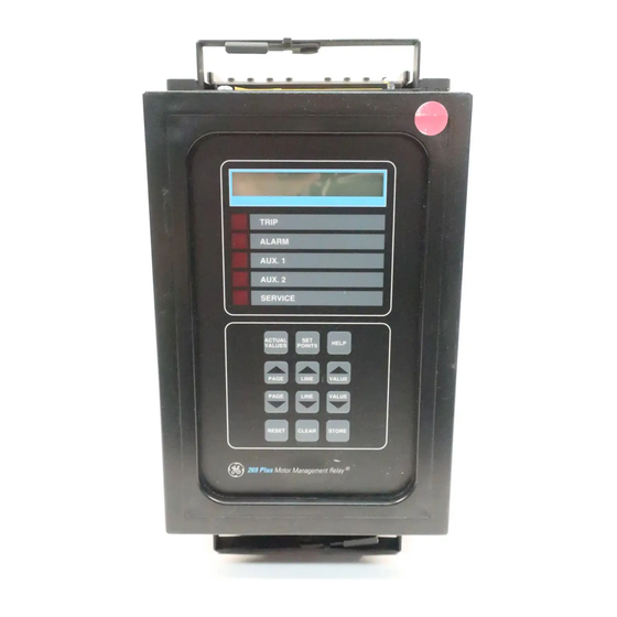
User Manuals: GE 269Plus Motor Management Relay
Manuals and User Guides for GE 269Plus Motor Management Relay. We have
1
GE 269Plus Motor Management Relay manual available for free PDF download: Instruction Manual
GE 269Plus Instruction Manual (218 pages)
Motor Management Relay
Brand:
GE
| Category:
Relays
| Size: 7.46 MB
Table of Contents
1. Introduction
5
Table of Contents
5
Motor Protection Requirements
9
Features
9
Introduction 1.1 Motor Protection Requirements
9
Table 1-1: 269Plus RELAY FEATURES
11
Typical Applications
12
Order Code / Information
13
Technical Specifications
14
Mpm Option Specifications
17
2 Installation
19
Physical Dimensions
19
Mounting
24
Table 2-1: 269Plus External Connections
25
External Connections
26
Control Power
30
Phase Ct Inputs
32
Table 2-2: Typical Ct Ratings
32
Ground Ct Input
34
Trip Relay Contacts
35
Alarm Relay Contacts
36
Auxiliary Relay #1 Contacts
36
Auxiliary Relay #2 Contacts
37
Rtd Sensor Connections
37
Emergency Restart Terminals
38
External Reset Terminals
39
Analog Output Terminals (Non-Isolated)
39
Differential Relay Terminals
39
Speed Switch Terminals
40
Programming Access Terminals
40
Rs485 Serial Communications Terminals
40
Display Adjustment
42
Front Panel Faceplate
42
Spare Input Terminals
42
Drawout Relay Option
44
Control Power (5/6/7/8)
47
Mpm Wiring
47
Meter Option Installation
47
D VT INPUTS (1-4)
48
F SERIAL COMMUNICATIONS PORT (COM1 - 46,47,48)
49
Mpm Analog Output
49
3 Setup and Use
57
Front Panel
57
Controls and Indicators
58
Table : 3-1 Controls and Indicators
58
Relay Display Modes
62
Actual Values Mode
63
Starts/Hour Timer
63
Table : 3-2 269P Lus Actual Values
63
Time between Starts Timer
63
Cause of Last Event
68
Cause of Last Trip
68
A STARTS/HOUR TIMER
71
B TIME between STARTS TIMER
72
Setpoints Mode
74
Table : 3-3 269P Lus Setpoints
75
Help Mode
99
Trip/Alarm Mode
100
Table 3-4: TRIP/ALARM MESSAGES and FAULT DIAGNOSIS
100
Phase Ct & Motor Full Load Current Setpoints
103
Acceleration Time Setpoint
103
Inhibits
104
Unbalance Setpoints
105
Ground Fault (Earth Leakage) Setpoints
106
Contactor/Breaker Wiring
107
Undercurrent Setpoints
108
Rapid Trip / Mechanical Jam Setpoints
108
Short Circuit Setpoints
108
Immediate Overload Alarm Setpoint
109
Stator Rtd Setpoints
109
Other Rtd Setpoints
110
Overload Curve Setpoints
112
Table 3-5: STANDARD OVERLOAD CURVE TRIP TIMES (in SECONDS)
112
Thermal Capacity Alarm
115
Thermal Memory
115
U/B Input to Thermal Memory
116
Rtd Input to Thermal Memory
117
Learned Cooling Times
118
Start Inhibit
118
Emergency Restart
119
Resetting the Relay
120
Single Shot Restart
120
Special External Reset
120
Relay Self-Test
121
Statistical Data Features
121
Factory Setpoints
121
Meter Option
122
Recommendations
124
The Phenomenon
124
Table 3-6: PRESET FACTORY RELAY CONFIGURATIONS and FUNCTIONS
125
Preset Configurations / Functions
126
4 Communications
127
Introduction
127
Modes of Operation
127
Physical Layer
127
Packet Format
129
The Handshake
130
Table 4-1: HANDSHAKE DATA
130
Supported Functions
132
Function 04H: Read Actual Values (Input Registers)
132
Function 16 (10H): Write Setpoint Values
132
Exception or Error Replies
133
Error Checking Code
134
Crc-16 Algorithm
134
Description
134
Sample Packet with Crc-16
135
Memory Map
135
Table : 4-2 269Plus Memory Map
136
Format Codes
150
Table : 4-3 Memory Map Format Codes
150
5 Relay Testing
157
Primary Injection Testing
157
Secondary Injection Testing
157
Phase Current Input Functions
158
Ground Fault Current Functions
160
Rtd Measurement Tests
160
Table 5-1: RTD RESISTANCE VS. TEMPERATURE
160
Power Failure Testing
161
Analog Current Output
161
Routine Maintenance Verification
161
Dielectric Strength (Hi-Pot) Test
162
Theory of Operation 6.1 Hardware
163
Hardware
164
Firmware
165
Relay Powered from One of Motor Phase Inputs
167
Control Power Loss Due to Short Circuit/Ground Fault
167
Using Flc Thermal Capacity Reduction Setpoint
167
Overview
169
Hardware & Software Requirements
169
Toolbar Summary
169
Menu Summary
170
Hardware Configuration
171
269Pc Installation
172
Startup and Communications Configuration
173
Entering Setponits
174
Saving Setpoints to a File
176
Loading Setponts from a File
177
Viewing Actual Values
178
Trending
180
Using the Troubleshooting Feature
181
Table : 9-1 Commissioning Table
183
269Plus Commissioning Summary
184
Revision History
187
Table 9-2: REVISION HISTORY TABLE
187
Description
189
Example
189
Thermal Model
191
269 Plus Rtd Bias Feature
192
Description
193
Two-Wire Rtd Lead Compensation
195
Description
197
Description
201
Dos
201
A 269PLUS GROUNDING
201
D RS485 COMMUNICATIONS PORT
202
Don'ts
203
Description
205
Plus Ct Withstand
207
Ct Size and Saturation
207
Transformers H
210
List of Figures
211
List of Tables
212
Advertisement
Advertisement
Related Products
GE MULTILIN 269 MOTOR MANAGEMENT RELAY Series
GE 239
GE 26936
GE 26980
GE 26970
GE 26925A
GE 26955
GE 26994
GE SPACEMAKER 26976
GE 26925C
GE Categories
Refrigerator
Ranges
Microwave Oven
Air Conditioner
Dishwasher
More GE Manuals
Login
Sign In
OR
Sign in with Facebook
Sign in with Google
Upload manual
Upload from disk
Upload from URL