Sign In
Upload
Manuals
Brands
GE Manuals
PCI Card
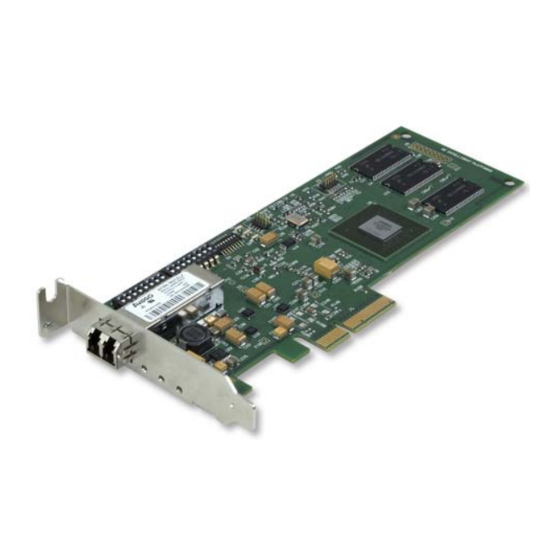
PCIE-5565PIORC*
GE PCIE-5565PIORC* Manuals
Manuals and User Guides for GE PCIE-5565PIORC*. We have
1
GE PCIE-5565PIORC* manual available for free PDF download: Hardware Reference Manual
GE PCIE-5565PIORC* Hardware Reference Manual (70 pages)
Ultrahigh Speed Fiber-Optic Reflective Memory with Interrupts
Brand:
GE
| Category:
PCI Card
| Size: 1.76 MB
Table of Contents
Table of Contents
3
List of Figures
5
List of Tables
6
Overview
8
Figure 1 Block Diagram of PCIE-5565PIORC
9
Figure 2 Typical Reflective Memory Network
10
1 Handling and Installation
15
Unpacking Procedures
15
Handling Precaution
15
Switch S1 and S2 Configuration
16
Before Installation Switch S1 and S2 Configuration
16
Table 1-1 Example Node ID Switch S2 RFM-5565
17
Table 1-2 Switch S1 Configuration RFM-5565
17
Figure 1-1 S1 and S2 Location PCIE-5565PIORC
18
Physical Installation
19
Figure 1-2 Installing the PCIE-5565PIORC
19
Front Panel Description
20
Figure 1-3 Low Profile and Standard Front Panels of the PCIE-5565PIORC
20
LED Description
21
Cable Configuration
21
Connector Specification (Singlemode and Multimode)
21
Table 1-3 LED Descriptions
21
Table 1-4 Cable Specifications for Multimode and Singlemode
21
Figure 1-4 LC Type Fiber-Optic Cable Connector
22
Figure 1-5 Example: Six Node Ring Connectivity PCIE-5565PIORC
22
2 Theory of Operation
23
Basic Operation
23
Front Bezel LED Indicators
23
RFM-5565 Register Sets
24
Reflective Memory RAM
24
Interrupt Circuits
25
Figure 2-1 Interrupt Circuitry Block Diagram
26
Network Interrupts
27
Redundant Transfer Mode of Operation
27
Rogue Packet Removal Operation
28
3 Programming
29
PCI Configuration Registers
30
Table 3-1 PCI Configuration Registers
30
Table 3-2 PCI Configuration ID Registers
30
Table 3-3 PCI Command Register
31
Table 3-4 PCI Status Register
32
Table 3-5 PCI Revision ID Register
32
Table 3-6 PCI Class Code Register
33
Table 3-7 PCI Cache Line Size Register
33
Table 3-8 PCI Latency Timer Register
33
Table 3-9 PCI Header Type Register
33
Table 3-10 PCI Built-In Self Test Register
34
Table 3-11 PCI Base Address Register 0 for Access to Local Configuration Registers
34
Table 3-12 PCI Base Address Register 1 for Access to Local Configuration Registers
35
Table 3-13 PCI Base Address Register 2 for Access to RFM Control and Status Registers
35
Table 3-14 PCI Base Address Register 3 for Access to Reflective Memory
36
Table 3-15 PCI Base Address Register 4
36
Table 3-16 PCI Base Address Register 5
36
Table 3-17 PCI Cardbus CIS Pointer Register
37
Table 3-18 PCI Subsystem Vendor ID Register
37
Table 3-19 PCI Subsystem ID Register
37
Table 3-20 PCI Expansion ROM Base Register
37
Table 3-21 PCI Capability Pointer Register
37
Table 3-22 PCI Interrupt Line
38
Table 3-23 PCI Interrupt Pin
38
Table 3-24 MSI Capability Structure
38
Table 3-25 Message Control Bit Definition
38
Table 3-26 Power Management Capability Structure
39
Table 3-27 Pcie Capability Structure
39
Table 3-28 Pcie Capabilities Register Bit Definition
39
Table 3-29 Device Capabilities Register Bit Definition
39
Table 3-30 Device Control Register Bit Definition
40
Table 3-31 Device Status Register Bit Definition
41
Table 3-32 Link Capabilities Register Bit Definition
41
Table 3-33 Link Control Register Bit Definition
41
Table 3-34 Link Status Register Bit Definition
42
Local Configuration Registers
43
Table 3-35 Local Configuration and DMA Control Registers
43
Table 3-36 Mode/Dma Arbitration Register
44
Table 3-37 Big/Little Endian Descriptor Register
44
Table 3-38 Interrupt Control and Status Register
45
Table 3-39 INTCSR Interrupt Enables
45
Table 3-40 INTCSR Interrupt Status
45
Table 3-41 PCI Core/Features Revision ID
46
Table 3-42 DMA Channel 0 Mode Register
46
Table 3-43 DMA Channel 0 PCI Address Register
46
Table 3-44 DMA Channel 0 Local Address Register
46
Table 3-45 DMA Channel 0 Transfer Size (Bytes) Register
47
Table 3-46 DMA Channel 0 Descriptor Pointer Register
47
Table 3-47 DMA Channel 0 Command/Status Register
47
Table 3-48 DMA Channel 0 PCI Dual Address Cycles Upper Address
48
Table 3-49 PCI PIO Direct Slave Local Address Range
48
Table 3-50 PCI PIO Direct Slave Local Base Address (Remap)
48
RFM Control and Status Registers
49
Table 3-51 Memory Map of the Local Control and Status Registers
49
Board ID Register
50
Board Revision Build Register
50
Board Revision Register
50
Local Control and Status Register 1
50
Node ID Register
50
Table 3-52 Local Control and Status Register 1
50
Local Interrupt Control Registers
54
Table 3-53 Local Interrupt Status Register
54
Network Target Data Register
57
Network Target Node Register
57
Table 3-54 Local Interrupt Enable Register
57
Interrupt 1 Sender Data FIFO
58
Interrupt 1 Sender ID FIFO
58
Network Interrupt Command Register
58
Table 3-55 Network Interrupt Command Register
58
Interrupt 2 Sender Data FIFO
59
Interrupt 2 Sender ID FIFO
59
Interrupt 3 Sender Data FIFO
59
Interrupt 3 Sender ID FIFO
59
Interrupt 4 Sender Data FIFO
59
Interrupt 4 Sender ID FIFO
59
Figure 3-1 Block Diagram of the Network Interrupt Reception Circuitry
60
Example of a Block DMA Operation for RFM-5565
61
Example of a Scatter-Gather DMA Operation for RFM-5565
62
Example of a PCI PIO Sliding Window Operation for RFM-5565
64
Example of Network Interrupt Handling
66
Setup
66
Servicing Network Interrupts
66
Maintenance
67
Compliance Information
68
Advertisement
Advertisement
Related Products
GE PCI-5565PIORC*
GE Profile PCR06BATSS
GE Profile PCF23RGW
GE Profile PCF25PGW
GE PCT23SGRCSS and
GE PCGB980
GE PCB987
GE PCS940YMFS
GE Profile PCST22U1
GE PCF23MGWCCC
GE Categories
Refrigerator
Ranges
Microwave Oven
Air Conditioner
Dishwasher
More GE Manuals
Login
Sign In
OR
Sign in with Facebook
Sign in with Google
Upload manual
Upload from disk
Upload from URL