Sign In
Upload
Manuals
Brands
GE Manuals
Medical Equipment
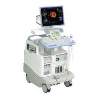
Vivid 7 PRO
GE Vivid 7 PRO Manuals
Manuals and User Guides for GE Vivid 7 PRO. We have
1
GE Vivid 7 PRO manual available for free PDF download: Service Manual
GE Vivid 7 PRO Service Manual (510 pages)
Brand:
GE
| Category:
Medical Equipment
| Size: 16.89 MB
Table of Contents
Table of Contents
9
Overview
25
Purpose of Chapter 1
25
Purpose of Service Manual
25
Typical Users of the Service Manual
26
VIVID 7 / VIVID 7 PRO Models Covered by this Manual
26
Purpose of Operator Manual(S)
31
Important Conventions
32
Conventions Used in Book
32
Standard Hazard Icons
33
Product Icons
34
Safety Considerations
36
Introduction
36
Human Safety
36
Mechanical Safety
36
Electrical Safety
37
Labels Locations
38
Dangerous Procedure Warnings
60
Lockout/Tagout Requirements (for USA Only)
60
EMC, EMI, and ESD
61
Electromagnetic Compatibility (EMC) and Interference (EMI)
61
CE Compliance
61
Electrostatic Discharge (ESD) Prevention
61
Customer Assistance
62
Contact Information
62
System Manufacture
63
Pre-Installation
65
Overview
65
Purpose of Chapter 2
65
General Console Requirements
66
Console Environmental Requirements
66
Electrical Requirements
67
EMI Limitations
68
Probes Environmental Requirements
70
Time and Manpower Requirements
70
Facility Needs
71
Purchaser Responsibilities
71
Required Facility Needs
72
Desirable Features
73
Minimal Floor Plan Suggestion
73
Networking Pre-Installation Requirements
74
Overview
77
Purpose of Chapter 3
77
Installation Reminders
77
Average Installation Time
77
Installation Warnings
78
Receiving and Unpacking the Equipment
79
Introduction
79
Receiving VIVID 7 / VIVID 7 PRO
80
Introduction
80
Unpacking VIVID 7 / VIVID 7 PRO
81
Transportation Box Dimensions
83
Preparing for Installation
84
Physical Inspection
84
EMI Protection
84
Completing the Installation
84
System Specifications
84
Electrical Specifications
85
Connect Footswitch
86
Connect Telephone Line to Modem Connector
86
Connect ECG
87
Connect Phono
87
Connect Pulse Pressure Transducer
88
Connect Ethernet
88
Probe Connection
89
Power On/Boot up
90
Power Shut down
93
Switching off the Unit
93
Configuration
97
VIVID 7 / VIVID 7 PRO Configuration
98
Service Screen
104
Optional Peripherals/Peripheral Connection
108
Available Probes
108
Video Specification
108
Software Options Configuration
109
Connectivity
111
Introduction
111
Physical Connection
111
Connectivity Setup
113
Installation Paperwork
132
User Manual(S)
132
Complete the Post Delivery Check List
133
Post Delivery Check List
134
Functional Checks
135
Overview
135
Purpose of Chapter 4
135
Special Equipment Required
135
General Procedures
136
Power ON/ Boot up
136
Power Shut down
139
Using Removable Media
143
Labeling Removable Media
144
Formatting Removable Media
145
Verifying Removable Media
145
Archiving and Loading Presets
146
Functional Checks
148
Preparation
148
Basic Controls
148
Performance Tests
150
2D Mode (B Mode) Checks
151
M Mode Checks
158
Color Mode Checks
162
Doppler Mode Checks
168
Tissue Velocity Imaging (TVI) Checks
174
Contrast Checks
180
Stress Echo
180
Measurements and Multi Image Checks
181
Multi Image Checks
183
Probe/Connectors Check
184
ECG Check
185
Cineloop Check
186
Backend Processor Checks
190
Peripheral Checks
191
Mechanical Functions Checks
195
Application Turnover Check List
197
Software Configuration Checks
197
Power Supply
198
Power Supply Test Procedure
198
Power Supply Adjustment
198
Components and Functions (Theory)
201
Overview
201
Purpose of Chapter 5
201
General Information
202
Block Diagram
203
Front End Processor
204
General Information
204
Front End Bus
204
Phased and Linear Array Front End
204
Transmitter Power Supply
205
MID Processors
205
Major Sub-Systems in VIVID 7 / VIVID 7 PRO
211
Front End Subsystem
212
MID Processors
213
Back End Processor
214
Introduction
214
Signal Flow and Processing
214
Location of the Back End Processor
214
BEP-1 Block Diagram
215
BEP-1 Description
216
BEP-2 Block Diagram
217
BEP-2 Description
218
PCVIC Card
219
UPS Battery Operation
219
Internal Storage Devices
220
Inputs
220
Outputs
222
Patient I/O (Physio)
223
Internal I/O
224
Location in the Unit
226
Leds
226
Fuses
226
Jumpers and Dip-Switches
226
Inputs
227
Outputs
229
Top Console
231
Peripherals
232
On-Board Peripherals
232
External Peripherals
232
Modem
233
Power Distribution
234
Overall AC Power Distribution
234
Overview
235
AC Power Distribution Box (PWB)
235
DC Power
237
TX Power Supply
241
Circuit Boards
244
Overview
244
Relay Board, RLY
245
Transmitter Board, TX128
247
Front End Controller Board, FEC-2
256
Transducer Bus Boards, XD BUS Boards
261
RF & Tissue Processor Board, RFT
262
Spectrum Doppler Processor Board, SDP
266
Image Port 2 Board, IMP2
270
Backend Processor
274
Patient I/O
278
Internal I/O
280
External I/O
287
Interconnect Cabling
290
Motherboard (Back Plane)
292
Modem
293
Video Specifications
295
Pal
295
Ntsc
295
System Logs
295
Board Rack Cooling System
296
General Description
296
Location in the Unit
296
Top Console Movement
297
Transportation of VIVID 7 / VIVID 7 PRO
297
Location in the Unit
298
General Description VIVID 7 PRO
300
Location in the Unit VIVID 7 PRO
300
Common Service Platform
301
Introduction
301
Ilinq Interactive Platform Features
301
Global Service User Interface (GSUI)
302
Overview
305
Purpose of Chapter 6
305
Power Supply Adjustments
305
Monitor Adjustments
306
Cautions and Warnings
306
Access to Adjustments
306
Adjustment Procedure(S)
306
Front End Alignment Procedure
307
When to Do a Front End Alignment Procedure
307
Procedure
307
Direction Lock and Brake Adjustment
308
Front Caster Brakes Adjustment Procedure
308
Direction Lock Adjustment Procedure
309
Rear Brakes Adjustment
311
Overview
313
Purpose of Chapter 7
313
Service Software Tools
313
Special Service Tool
313
Frequently Asked Questions
314
Diagnostics
315
Diagnostic Procedure Summary
315
Common Service Diagnostic Interface (Ultrasound Interface)
316
Service Home Page
317
Description of Screens
318
Error Logs
319
Utilities
329
Diagnostics
335
Image Quality
340
Calibration
341
Configuration
343
Utilities
344
Replacement
354
Home
355
Exit from Diagnostics
355
Common Diagnostics
356
Common Diagnostics - Utilities
357
PC (Backend Processor) Diagnostics, Non-Interactive Tests
359
PC (Backend Processor) Diagnostics, Interactive Tests
365
Acquisition Diagnostics
371
System Test Diagnostics Summary
371
Start System Test
371
Beamformer Calibration
372
System Test
373
Beamformer Calibration (Front End Alignment)
377
Troubleshooting
379
Console Troubleshooting Trees
379
Overview
383
Purpose of Chapter 8
383
Warnings
383
Plastic Parts Replacement Procedures
384
Overview of Covers and Bumpers
384
Side Covers Replacement Procedure
385
Front Cover Replacement Procedure
387
Filter Cover Replacement Procedure
388
Filter Replacement Procedure
389
Lower Rear Cover Replacements Procedure
390
SW Loading Procedure
391
Introduction
391
Customer Provided Prerequisite
391
Tools Provided with Unit or after a Software Upgrade
392
Preparation
393
Prepare MO Disks for Image Storage
394
Move Images
395
Prepare MO Disk for Patient Archive
398
Backup of Patient Database and User Presets
399
Recording of SW Option Keys, TCP/IP and Service Settings
400
Software Installation
406
Advertisement
Advertisement
Related Products
GE Vivid 7, Vivid E9
GE Vivid 7
GE Vivid 3 Pro
GE Vivid E9
GE Vivid q N
GE VIVID 3 N RFI
GE Vivid i
GE Vivid e
GE Vivid S5
GE Vivid E9 Series
GE Categories
Refrigerator
Ranges
Microwave Oven
Air Conditioner
Dishwasher
More GE Manuals
Login
Sign In
OR
Sign in with Facebook
Sign in with Google
Upload manual
Upload from disk
Upload from URL