Sign In
Upload
Manuals
Brands
Hitachi Manuals
Air Conditioner
RAS-14FSXN
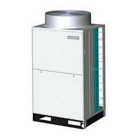
Hitachi RAS-14FSXN Air Conditioning Manuals
Manuals and User Guides for Hitachi RAS-14FSXN Air Conditioning. We have
1
Hitachi RAS-14FSXN Air Conditioning manual available for free PDF download: Service Manual
Hitachi RAS-14FSXN Service Manual (367 pages)
Brand:
Hitachi
| Category:
Air Conditioner
| Size: 18.4 MB
Table of Contents
Table of Contents
3
1 General Information
9
Copyright
9
Introduction
9
Environment-Friendly Units
9
Safety
10
Symbols Used
10
Product Guide
11
Classification of Outdoor Unit Models and CH Units
11
Product Guide: Outdoor Units
11
Accessory Code List
13
Unit Installation
14
Outdoor Unit
15
Preliminary Conditions for Positioning of Outdoor Unit
15
Transport, Lifting and Handling of the Units
15
Installation Space RAS-(8-18)FSXN
17
Center of Gravity
18
Installation
18
Foundation and Anchorage of Outdoor Unit
27
Units
29
Transportation and Handling CH Units
29
Unit Installation
29
3 Piping Work and Refrigerant Charge
37
Outdoor Unit
37
Refrigerant Pipe Selection
37
Copper Pipes, Sizes, Connection and Insulation
37
Pipe Connection Kit
40
Precautions for the Installation of the Outdoor Unit
45
General Instructions on the Installation of Refrigerant Pipes
46
Refrigerant Pipe Connection for Heat Pump Systems (2 Pipes)
48
Refrigerant Pipe Connection for Heat Recovery Systems (3 Pipes)
56
Refrigerant Charge
65
Precautions in the Event of Refrigerant Leaks
70
Drainage Pipes
71
Unit
73
Considerations
73
Piping Materials
73
Cautions for Piping Connection Work
73
Refrigerant Piping Work
74
4 Electrical Wiring
79
Outdoor Unit
79
General Information
79
General Verifications
79
Connection of the Power Supply Circuits
80
Setting of the DSW Switches on PCB1
85
Electrical Wiring Diagram RAS-(8-18)FSXN
89
Unit
90
General Information
90
General Verifications
90
Electrical Wiring Connection CH Units
90
5 Control System
95
Cycle Control
95
Compressor Operation Control
96
Heat Exchanger Mode Control
101
Outline of the Control System
102
Standard Operation Sequence
104
Cooling Operation
104
Cooling Operation (Continued)
105
Dry Operation
106
Dry Operation (Continued)
107
Antifreeze Protection Control During the Cooling or Dry Operation
108
Heating Operation
109
Heating Operation (Continued)
110
Defrost Operation
111
Excessive High Discharge Air Temperature Prevention Control
112
Protection Control
113
Control of CH Unit (CH-(6.0/10.0)N1)
116
Control and Safety Devices
118
Outdoor Unit
118
Unit
118
6 Optional Functions
120
Setting Method
120
External Input and Output Setting
120
External Input Function Setting
122
External Output Function Setting
126
Function Setting
129
Indoor Unit Fan Control During the Thermo-OFF in Heating Mode
136
Night-Shift (Low Noise)
137
Cancellation of the Outdoor Ambient Temperature Limit
138
Defrost for Cold Area (Change of Defrost Condition)
139
Slo Defrost Setting
139
Cancellation of Hot Start
139
Demand Function Setting
139
Wave Function Setting
140
Cold Draft Protection
140
Adjustment of Fan Rotation
140
7 Test Run
142
Preliminary Checks
142
Test Run
143
Before the Test Run
143
Test Run Using the Remote Control Switch
144
Test Run from the Outdoor Unit
144
Checking at Test Run
146
Refrigerant Cycle Checklist
147
Automatic Judgement System for Refrigerant Amount
149
Reset for Accumulated Operation Time of Compressor 1-2 after Maintenance (Cuj1-Cuj2)
151
Test Run Check List
152
8 Troubleshooting
154
Initial Troubleshooting
154
Checking the Electrical Wires and the Power Source
154
Checking by 7-Segment Display
155
Checking of the Alarm Code History
156
Emergency Operation
159
Failure of the Power Supply to the Indoor Units and the Remote Control Switch
164
Abnormal Transmission between the Remote Control Switch and the Indoor Unit
165
Abnormal Operation of the Devices
166
Procedure for Troubleshooting
174
Alarm Codes
174
Troubleshooting by Alarm Code
176
Alarm Codes
176
Troubleshooting in the Check Mode by Using the Remote Control Switch
244
Troubleshooting by Using the 7-Segment Display
251
RSW, Dsws and Leds Functions
263
Checking Procedures for each Main Part
268
Self-Checking of PCB Using the Remote Control
268
Self-Checking of the Remote Control Switch
271
Checking Procedures for Other Main Parts
273
9 Spare Parts
281
Cabinet and Fan Components for Outdoor Units
281
Cabinet and Fan Components for RAS-(8-12)FSXN
281
Cabinet and Fan Components for RAS-(14-18)FSXN
283
Refrigerant Cycle Components for Outdoor Units
285
Refrigerant Cycle Components for RAS-(8-12)FSXN
285
Refrigerant Cycle Components for RAS-(14-18)FSXN
288
Electrical Box Components for RAS-(8-18)FSXN
291
Sub Electrical Box Components for RAS-(14-18)FSXN
293
Refrigerant Cycle and Electrical Parts for CH Units
294
10 Servicing
296
Removing the Front Service Cover
296
Removing the Upper Cover
297
Removing the Electrical Box Cover
298
Removing the Electrical Box Cover for RAS-(8-12)FSXN
299
Removing the Electrical Box Cover for RAS-(14-18)FSXN
299
Removing the Electrical Box
299
Removing the Electrical Box for RAS-(8-12)FSXN
299
Removing the Electrical Box for RAS-(14-18)FSXN
299
Removing the Electrical Box Stay
300
Removing the Electrical Box Stay for RAS-(14-18)FSXN
300
Removing the Air Grille
301
Removing the Outdoor Fan
302
Removing the Compressor
304
Replacing the Refrigerant Oil
312
No Clogging in Return Oil Circuit
312
Clogging in Return Oil Circuit
313
Replacing the Return Oil Circuit
315
Removing the Coils
316
Removing the Expansion Valve Coil (MV1, MVB)
317
Removing the Solenoid Valve Coil (SVA, SVG)
318
Removing the Solenoid Valve
318
Removing the Reversing Valve Coil (RVR1, RVR2)
319
Removing the Reversing Valve
319
Removing the Stop Valve
321
Removing the High Pressure Switch, High Pressure Sensor and Low Pressure Sensor
322
Removing the High Pressure Switch (PSH1, PSH2)
322
Removing the High Pressure Sensor (Pd) and Low Pressure Sensor (Ps)
323
Removing the Liquid Pipe Thermistor
324
Removing the Ambient Temperature Thermistor
326
Removing Other Electrical Components
327
Removing the PCB1 and Electrical Components for the Electrical Box
327
Removing the PCB2 for the Inverter
329
Removing the Diode Module and Transistor Module
329
Removing the Fan Controller
331
Fitting the Electrical Box
331
11 Electrical Checks of the Main Parts
333
Inverter
333
Inverter Specifications
333
Inverter Power Unit Structure
334
Protection Function
335
Overload Protection Control
336
Scroll Compressor
337
Reliable Mechanism for Low Vibration and Low Sound
337
Compression Principles
337
Structure
337
Compressor Type
338
Thermistors
339
Thermistor Positions
339
Thermistor for the Temperature of the Upper Part of the Compressor
340
Thermistor for the Outdoor Ambient Temperature
341
Advertisement
Advertisement
Related Products
Hitachi RAS-14FSXN1E
Hitachi RAS-14FSXNH
Hitachi RAS-14FSXNHE
Hitachi RAS-14LH1(B)
Hitachi RAS-14SH4
Hitachi RAS-14XH1
Hitachi RAS-140RNCCRW
Hitachi RAS-14CH7
Hitachi RAS-14G5
Hitachi RAS-14AH1
Hitachi Categories
Projector
Air Conditioner
Drill
Power Tool
TV
More Hitachi Manuals
Login
Sign In
OR
Sign in with Facebook
Sign in with Google
Upload manual
Upload from disk
Upload from URL