Sign In
Upload
Manuals
Brands
Honeywell Manuals
Transmitter
SmartLine ST 800
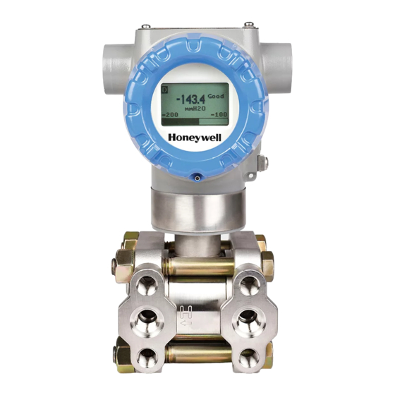
User Manuals: Honeywell SmartLine ST 800 Transmitter
Manuals and User Guides for Honeywell SmartLine ST 800 Transmitter. We have
1
Honeywell SmartLine ST 800 Transmitter manual available for free PDF download: User Manual
Honeywell SmartLine ST 800 User Manual (144 pages)
Pressure Transmitters
Brand:
Honeywell
| Category:
Transmitter
| Size: 4.1 MB
Table of Contents
Table of Contents
7
Introduction
11
Overview
11
Features and Options
11
Physical Characteristics
11
Table 1 - Features and Options
11
Functional Characteristics
12
Figure 1 - ST 800 Major Assemblies
12
Figure 2 - Electronics Housing Components
12
ST 800 Transmitter Name Plate
13
Safety Certification Information
13
Transmitter Adjustments
13
Figure 3 -Typical ST 800 Name Plate
13
Display Options
14
Optional 3-Button Assembly
14
Table 2 - Available Display Characteristics
14
Application Design
15
Overview
15
Accuracy
15
Diagnostic Messages
15
Table 3 - ST 800 Standard Diagnostics Messages
15
Safety Integrity Level (SIL)
16
Plugged Impulse Line Detection (PILD)
16
Installation and Startup
17
Installation Site Evaluation
17
Honeywell Versatilis Configurator
17
Display Installation Precautions
18
Mounting ST 800 Smartline Pressure Transmitters
18
Summary
18
Figure 4 - Typical Bracket Mounted and Flange Mounted Installations
18
Mounting Dimensions
19
Bracket Mounting Procedure
19
Figure 5 - Angle Mounting Bracket Secured to a Horizontal or Vertical Pipe
19
Figure 6 - Inline Model Mounted to an Optional Bracket
20
Figure 7 - Rotating the Electronics Housing
20
Mounting Transmitters with Small Absolute or Differential Pressure Spans
21
Flange Mounting
21
Figure 8 - Using a Spirit Balance to Level a Transmitter
21
Flush Mounting Procedure
22
Figure 9 - Tank-Flange Mounted Transmitter
22
Figure 10 - Typical Flush and Flange Mounted Installations
22
Remote Diaphragm Seal Mounting Information
23
Figure 11 - Representative Remote Diaphragm Seal Transmitter Installation
23
Table 4 - Flange Mounting Guidelines
23
Piping the ST 800 Transmitter
24
Piping Arrangements
24
Figure 12 - Typical 3-Valve Manifold with Blow-Down Piping
24
Table 5 - Remote Diaphragm Mounting Details
24
Suggestions for Transmitter Location
25
General Piping Guidelines
25
Procedure to Install Flange Adapters
25
Table 6 - Suggested Connection Locations
25
Wiring a Transmitter
26
Overview
26
Figure 13 - Flange Adapter Removal and Replacement
26
Figure 14 - Transmitter Operating Ranges
26
Figure 15 - Transmitter 3-Screw Terminal Board and Grounding Screw
27
Digital System Integration Information
28
Wiring Variations
28
Wiring Procedure
28
Lightning Protection
28
Supply Voltage Limiting Requirements
28
Process Sealing
29
Explosion-Proof Conduit Seal
29
Startup
29
Overview
29
Startup Tasks
29
Output Check Procedures
30
Constant Current Source Mode Procedure
30
Figure 16 - Current Loop Test Connections
30
Operation
32
Overview
32
Three-Button Operation
32
Figure 17 - Three-Button Option
32
Menu Navigation
33
Table 7 - Three-Button Option Functions
33
Data Entry
34
Editing a Numeric Value
34
Selecting a New Setting from a List of Choices
34
Table 8 - Three-Button Data Entry
34
The Advanced Display Menus
35
Table 9 - Advanced Display Main Menu Structure
35
Table 10 - Diagnostics Menu
36
Table 11 - Display Setup Menus
38
Table 12 - Calibration Menus
43
Table 13 - Transmitter Setup Menus
46
The Standard Display Menu
50
Table 14 - Information Menus
50
Table 15 - the Standard Display Menus
51
Table 16 - ST 800 Standard Transmitter: Standard Display Menus Russian Language
68
The Basic Display Menu
86
Table 17 - the Basic Display Menus
86
Selecting a New Setting from a List of Choices
90
Three Button Operation with no Display Installed
90
Zero Adjustment
90
Span Adjustment
90
Changing the Default Failsafe Direction
91
And Analog Differences
91
Procedure to Establish Failsafe Operation
91
Figure 18 - Locating the Failsafe and Write Protect Jumpers
92
Table 18 - Hart and de Failsafe and Write Protect Jumpers
92
Table 19 - Fieldbus Simulation and Write Protect Jumpers
93
Monitoring the Basic, Standard and Advanced Displays
94
Basic Display
94
Standard Display
94
Figure 19 - Basic Display with Process Variable Format
94
Figure 20 - Standard Display with Process Variable Format
94
Advanced Display
95
Figure 21 - Advanced Display Formats with the Process Variable
95
Table 20 - Advanced Display with PV Format Display Indications
96
Button Operation During Monitoring
97
Maintenance
98
Overview
98
Preventive Maintenance Practices and Schedules
98
Inspecting and Cleaning Barrier Diaphragms
98
Figure 22 - DP Transmitter Head Disassembly
99
Figure 23 - Head Bolt Tightening Sequence
100
Table 21 - Head Bolt Torque Values
100
Replacing the Communication Module
101
Figure 24 - PWA Replacement
101
Replacing the Meter Body
103
Figure 25 - Disassembly for Meter Body Replacement
103
Figure 26 - Hardware Location to Remove the Meter Assembly
104
Figure 27 - Meter Body Reassembly
105
Figure 28 - Head Bolt Tightening Sequence
105
PILD Option Licensing
106
Calibration
107
Recommendations for Transmitter Calibration
107
Calibration Procedures
107
Dual/Triple Cal
107
Troubleshooting
108
Overview
108
Critical Diagnostics Screens
108
Fault Conditions and Recommended Corrective Actions
108
Figure 29 - Local Display Fault Diagnostic Conditions
108
Table 22 - Fault Conditions and Recommended Corrective Actions
108
Parts List
110
Overview
110
Table 23 - Summary List of Recommended Spare Parts
110
Figure 30 - Angle and Flat Bracket Parts
111
Figure 31 - Electronic Housing, Display End
112
Table 24 - Angle and Flat Bracket Parts
112
Figure 32 - Electronic Housing, Terminal Block End
113
Table 25 - Transmitter Major Assemblies
113
Figure 33 - Transmitter Major Assemblies
114
Table 26 - ST 800 Models STD810, 820, 825, 830 & 870
115
Figure 34 - ST 800 Models STD810, 820, 825, 830, & 870
117
Table 27 - Parts for STG830, 840, 870 and STA822, 840 Transmitter Body
118
Figure 35 - STG830, 840, 870, and STA822, 840 Transmitter Body
120
Figure 36 - Inline Gauge and Inline Atmospheric Display Bodies
121
Figure 37 - Flush Mount Meter Body
121
Table 28 - Inline Gauge and Inline Atmospheric Meter Body Parts
121
Table 29 - Flush Mount Meter Body Parts
121
Figure 38 a - Extended Flange Design
122
Table 30 - Flange-Mounted Meter Body Parts
122
Figure 39 - Pseudo Flange Design
123
Figure 40 - Remote Seal Diaphragm
123
Product Certifications
124
Safety Instrumented Systems (SIS) Installations
124
European Directive Information (CE Mark)
124
Hazardous Locations Certifications
130
Control Drawing
134
Marine Approvals
139
Measurement Instruments Directive (MID)
139
Recycling and Disposal of Product
140
Glossary
141
Advertisement
Advertisement
Related Products
Honeywell SmartLine
Honeywell SMV 3000
Honeywell SMV800
Honeywell SmartEye Transmitter
Honeywell SmartLine STD720
Honeywell SmartLine STD770
Honeywell STGW73L
Honeywell STGW74L
Honeywell STAW74L
Honeywell SmartLine SLN 700 82 Series
Honeywell Categories
Thermostat
Controller
Control Unit
Security Camera
Accessories
More Honeywell Manuals
Login
Sign In
OR
Sign in with Facebook
Sign in with Google
Upload manual
Upload from disk
Upload from URL