Sign In
Upload
Manuals
Brands
Honeywell Manuals
Transmitter
SmartLine STT700 DE
Honeywell SmartLine STT700 DE Transmitter Manuals
Manuals and User Guides for Honeywell SmartLine STT700 DE Transmitter. We have
2
Honeywell SmartLine STT700 DE Transmitter manuals available for free PDF download: User Manual, Quick Start Installation Manual
Honeywell SmartLine STT700 DE User Manual (114 pages)
STT700 Series HART/DE Option
Brand:
Honeywell
| Category:
Transmitter
| Size: 3.57 MB
Table of Contents
Table of Contents
5
1 STT700 Physical and Functional Characteristics
8
Overview
8
Features and Options
9
Table 1 - Features and Options
9
Figure 1 - STT700 HART Temperature Transmitter Module
10
Figure 2 - STT700 de Temperature Transmitter Module
10
Physical Characteristics
10
Functional Characteristics
11
STT700 Smartline Transmitter Nameplate
11
Figure 3 - Nameplate on the Side of the Transmitter
11
Safety Certification Information
12
Transmitter Adjustments
12
EU Meters Options
12
Figure 4 -Typical STT700 Nameplate
12
Table 2 - Available EU Meter Characteristics
12
2 Communication Modes
13
Overview
13
Digitally Enhanced (DE) Mode Communication
13
Figure 5 - de Mode Value Scaling
13
HART Mode Communication
14
Figure 6 - HART Point-To-Point and Multi-Drop Value Scaling
14
3 Configuration Tools and Interfaces
15
Overview
15
Pre-Requisites
15
Application Design, Installation, Startup, and Operation
15
Organization
15
MC Toolkit Participation
16
MC Toolkit Software Applications
16
Configuration Databases
16
Configuration
16
MC Toolkit Transmitter Electrical/Signal Connections
17
Figure 7 - MC Toolkit-Transmitter Electrical/Signal Connections
17
4 DE Transmitter Configuration
18
Configuration Personnel Requirements
18
MC Toolkit Software Application Overview
18
DE Transmitter Online Configuration
19
Uploading a Transmitter Configuration
19
Device Information Configuration
21
Table 3 - Device Information Parameters
21
General Configuration Parameters
22
Table 4 - General Configuration Parameters
22
DE-Specific Configuration Parameters
23
Table 5 - de Configuration Parameters
23
DE Auxiliary Configuration
24
DE Monitor Status
24
Table 6 - Monitor Parameters
25
Saving the Configuration to File
26
DE Online Configuration Summary
27
DE Transmitter Offline Configuration
27
Overview
27
DE Offline File Management
27
Save to a File
28
Downloading in de Offline Mode
28
DE Offline Parameterization
28
5 HART Transmitter Configuration
29
Overview
29
Personnel Requirements
29
Overview of FDC Homepage
30
Figure 8 - FDC Homepage
30
Table 7 - FDC Homepage Elements
30
Settings
31
Manage Dds
32
Offline Configuration
34
Online Configuration
34
Online Configuration Overview
34
Figure 9 - Device Homepage
35
Overview of Device Homepage
35
Table 8 - Device Health Status
35
Tabs on the Device Home Page
36
Using FDC for Various Device Operations
38
Device Configuration and Parameter Descriptions
40
Table 10 - Basic Configuration
40
Table 9 - HART Transmitter Parameters
40
Table 11 - Advanced Configuration
43
Table 12 - Monitor
51
Procedure to Enter the Transmitter Tag
57
Selecting the Process Variable (PV) Unit of Temperature Measurement
57
Setting PV URV, and LRV Values
58
Setting Range Values for Applied Temperature
58
Saving Device History
59
Exporting Device History Records to FDM
60
Custom Views
61
Exporting Device History Records to Documint
61
Offline Configuration
63
6 DE Calibration
66
Overview
66
Calibration Recommendations
66
Test Equipment Required for Calibration
66
Analog Output Signal Calibration
67
Figure 10 - Analog Output Calibration Test Setup
67
Calibrating Range Using the MC Toolkit
69
Conditions for Input Calibration
69
Input Calibration Procedures Description
69
Input Calibration Procedure
70
Correct Input at the Lower Range Value (LRV)
70
Figure 11 - Input Calibration Connections
70
Correct Input at URV
71
DE Output Calibration
73
Output Calibration Preparation
73
Figure 12 - Output Calibration Test Connections
73
Figure 13 - de Analog Mode Scaling and Test Connections
74
Manually Setting the Process Variable Range
76
Figure 14 - Setup to Manually Set the PV LRV and URV
76
Procedure to Reset Calibration
79
7 HART Calibration
81
About this Section
81
About Calibration
81
Equipment Required
81
Input Calibration Procedure
82
Correct Input at Sensor 1 / 2 Calibration High Point
84
Analog Output Signal Calibration
87
Calibrating Analog Inputs
88
Correcting the Low Calibration Point
88
Correcting the High Calibration Point
89
Resetting Calibration
89
STT700 Calibration Records
90
Table 13 - Calibration Records
90
8 HART Advanced Diagnostics
91
About this Section
91
Advanced Diagnostics
91
Transmitter Install Date
91
Table 14 - Viewing Advanced Diagnostics
91
PV Tracking Diagnostics
92
Table 15 - PV Tracking
92
Cold Junction Tracking
95
Table 16 - Cold Junction Tracking
95
CT Tracking Diagnostics
97
Table 17 - Core Temperature Diagnostics
97
Installation and Device Life
98
Operating Voltage Diagnostics
98
Table 18 - Installation and Device Life Diagnostics
98
Table 19 - Operating Voltage Diagnostics
98
Power up Diagnostics
99
Table 20 - Power up Diagnostics
99
9 Troubleshooting and Maintenance
100
HART Diagnostic Messages
100
Table 21 - HART Diagnostic Messages
100
DE Diagnostic Details
102
Table 22 - de Critical and Non-Critical Diagnostic Details
102
10 Dtms
104
Introduction
104
Components
104
Downloads
104
Procedure to Install and Run the DTM
104
STT700 Dashboard
105
STT700 Online Parameterization
105
Device Health
106
Device Icon / Honeywell Logo
106
Process Variables
106
Shortcuts
106
Basic Configuration Page
107
Device Information
107
Model Number
107
Device Assembly
107
STT700 Offline Parameterization
108
11 HART DD Binary File Format Compatibility Matrix
109
Glossary
110
Advertisement
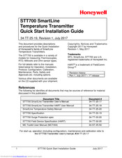
Honeywell SmartLine STT700 DE Quick Start Installation Manual (14 pages)
Temperature Transmitter
Brand:
Honeywell
| Category:
Transmitter
| Size: 0.97 MB
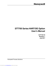
Table of Contents
Table of Contents
2
Installation
3
Features and Options
3
Table 1: Installation Considerations
3
Figure 1 - STT700 Temperature Transmitter (HART Left, de Right)
3
Mounting the Transmitter
4
Figure 2: DIN Rail Mounting
4
Table 2: Mounting Dimensions
5
Figure 3: Wall Mounting Dimensions
5
Figure 4: Pipe Mounting Dimensions
5
Figure 5: Spring Loading and Sensor Assembly
6
Wiring Connections and Power up
7
Figure 6: STT700 HART Transmitter Operating Ranges
7
Figure 7: STT700 de Transmitter Operating Ranges
7
Figure 8: STT 700 Terminal Connections
8
Figure 9: HART/DE Input Wiring Diagram for Single Sensor Connection
9
Input Sensor Wiring
9
Wiring Variations
9
Exlosion-Proof Conduit Seal
10
Figure 10: Wiring Diagram for HART Dual Sensor Connections
10
Lightning Protector
11
Figure 11: Lightning Protector Dimensions
11
Figure 12: Installation Without EU Meter
12
Figure 13: Installation with EU Meter
13
Advertisement
Related Products
Honeywell STT750 SmartLine
honeywell STT700 SmartLine
Honeywell STT700 STT700
Honeywell STT850 SMARTLINE
Honeywell STT25D
Honeywell STT25H
Honeywell STT25M
Honeywell STT850 Series
Honeywell STD974
Honeywell SmartLine STG770
Honeywell Categories
Thermostat
Controller
Control Unit
Security Camera
Accessories
More Honeywell Manuals
Login
Sign In
OR
Sign in with Facebook
Sign in with Google
Upload manual
Upload from disk
Upload from URL