Sign In
Upload
Manuals
Brands
Honeywell Manuals
Measuring Instruments
VERSAFLOW SONIC 1000/TWS 9000
Honeywell VERSAFLOW SONIC 1000/TWS 9000 Manuals
Manuals and User Guides for Honeywell VERSAFLOW SONIC 1000/TWS 9000. We have
1
Honeywell VERSAFLOW SONIC 1000/TWS 9000 manual available for free PDF download: Handbook
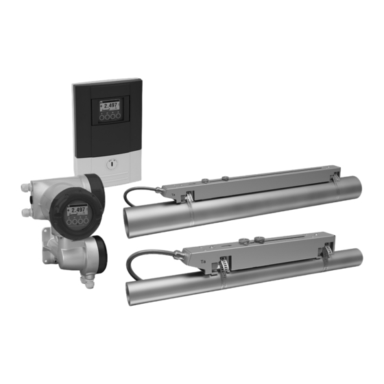
Honeywell VERSAFLOW SONIC 1000/TWS 9000 Handbook (210 pages)
Ultrasonic clamp-on flowmeter for liquids
Brand:
Honeywell
| Category:
Measuring Instruments
| Size: 16.73 MB
Table of Contents
Table of Contents
5
Safety Instructions
9
Software History
9
Intended Use
10
Certification
10
Safety Instructions from the Manufacturer
11
Copyright and Data Protection
11
Disclaimer
11
Product Liability and Warranty
12
Information Concerning the Documentation
12
Warnings and Symbols Used
13
Safety Instructions for the Operator
13
Device Description
15
Scope of Delivery
15
Device Description
17
Field Housing (Remote Version)
18
Wall Housing
18
Nameplates
19
Overview of the Nameplates (Examples)
19
Examples of Nameplates on the Signal Converter
19
Example Nameplate of the Flow Sensor Rail
20
Example of IO Nameplate
21
Installation
23
General Notes on Installation
23
Storage
23
Transport
23
Pre-Installation Requirements
24
General Requirements
24
Installation and Safety Instructions
24
Installation Conditions
26
Inlet, Outlet and Recommended Mounting Area
26
Horizontal (Long) Pipes
27
Bends in 2 or 3 Dimensions
27
T-Section
28
Bends
28
Open Feed or Discharge
29
Position of Pump
30
Position of Control Valve
30
Pipe Diameters and Sensor Rail(S) Construction
31
Pipe and Media Parameters
31
Installation of the Sensor Rail
32
General Mechanical Installation
32
Installation of Solid Contact Material
34
Standard Installation Options
35
Installation Instructions for Small and Medium Sensor Rail(S)
36
Mechanical Installation of Large Version
37
Installation of the up Sensor Rail
37
Installing the down Sensor Rail in V-Mode
39
Installation of the down Sensor Rail
40
Find the Transducer Location with a Fixed Reference Point
40
Determine the Transducer Position with a Paper Roll
41
Installing the down Sensor Rail in Z-Mode
43
Configuration Instructions for Large Sensor Rail(S)
44
Installation Instructions for X Mode Configuration
45
Installation of the Converter
46
Pipe Mounting
46
Wall Mounting
47
Turning the Display of the Field Housing Version
49
Install for Energy Measurement
50
Preparation of Energy Measurement
50
Program the Converter for Energy Measurement
51
Program the I/O Input
51
Program the Process Input
52
Program the Totalisers
53
Start Measurement
54
Electrical Connections
55
Safety Instructions
55
Laying Electrical Cables Correctly
55
Electrical Connections Signal Converter
56
Power Supply
57
Signal Converter Power Supply Connections
58
Example of Connecting the Cable Extension (Splitter) Box
59
Signal Cable to Converter
60
Modular Inputs/Outputs Connections
63
Inputs and Outputs, Overview
65
Combinations of the Inputs/Outputs (I/Os)
65
Description of the CG-Number
66
Fixed, Non-Alterable Input/Output Versions
67
Alterable Input/Output Versions
68
Description of the Inputs and Outputs
69
Control Input
69
Current Output
70
Pulse Output and Frequency Output
71
Status Output and Limit Switch
72
Current Input
73
Connection Diagrams of Inputs and Outputs
74
Important Notes
74
Description of the Electrical Symbols
75
Basic Inputs/Outputs
76
Modular Inputs/Outputs and Bus Systems
79
Ex I Inputs/Outputs
87
Current Input Active or Passive
91
HART ® Connection
94
Start-Up
95
Switching on the Power
95
General Instructions for Programming
95
Function Description Installation Menu
96
Start Measurement (Standard Setup)
98
Start Measurement of Large Version
99
Operation
101
Display and Operating Elements
101
Display in Measuring Mode with 2 or 3 Measured Values
103
Display for Selection of Submenu and Functions, 3 Lines
103
Display When Setting Parameters, 4 Lines
104
Display When Previewing Parameters, 4 Lines
104
Using an IR Interface (Option)
105
Menu Overview
106
Function Tables
120
Menu A, Quick Setup
120
Menu B; Test
122
Menu C; Setup
124
Set Free Units
140
Description of Functions
141
Reset Totaliser in the Menu "Quick Setup
141
Deleting Error Messages in the Menu "Quick Setup
141
Diagnosis Messages
142
Optical Keys
142
Graphic Page
142
Save Settings
142
Load Settings
142
Passwords
143
Date and Time
143
Low Flow Cutoff
143
Time Constant
144
Dual Phase Pulse Output
144
Timeouts in Programming Mode
144
Function 5: Reynolds Linearisation
145
Output Hardware
145
Status Messages and Diagnostic Information
146
Service
153
Periodic Maintenance
153
Regreasing of Transducers
153
Cleaning
153
Exchange of Electronics Unit
153
Before and after Opening
154
Field Version
155
Wall Version
157
Replacing the Mains Fuse
159
Field Version
159
Wall Version
159
Spare Parts Availability
160
Availability of Services
160
Returning the Device to the Manufacturer
160
General Information
160
Form (for Copying) to Accompany a Returned Device
161
Disposal
161
Disassembly and Recycling
162
Remove the Connection And/Or Other Cable(S)
163
Disassembling the Sensor Rail
165
Overview of the Sensor Materials and Components
167
Overview of the Converter Materials and Components
168
Technical Data
171
Measuring Principle
171
Technical Data
172
Dimensions and Weight
183
Housing
183
Clamp-On Sensor Rail
184
Mounting Plate of Field Housing
186
Mounting Plate of Wall-Mounted Housing
186
Description of HART Interface
187
General Description
187
Identification Codes and Revision Numbers
187
Connection Variants
188
Point-To-Point Connection - Analogue / Digital Mode
189
Multi-Drop Connection (2-Wire Connection)
190
Multi-Drop Connection (3-Wire Connection)
191
Inputs/Outputs and HART Dynamic Variables and Device Variables
192
Remote Operation
194
Online/Offline Operation
194
Parameters for the Basic Configuration
195
Units
195
Field Communicator 375/475 (FC 375/475)
196
Installation
196
Operation
196
Asset Management Solutions (AMS)
197
Installation
197
Operation
197
Process Device Manager (PDM)
198
Installation
198
Operation
198
HART Menu Tree
199
HART Menu Tree - Field Communicator HART Application
199
HART Menu Tree AMS - Device's Context Menu
200
HART Menu Tree PDM - Menu Bar and Working Window
201
Process Variables Root Menu
202
Diagnostic Root Menu
202
Device Root Menu
203
Offline Root Menu
208
Description of HART Interface
209
Advertisement
Advertisement
Related Products
Honeywell AutoSet 1500
Honeywell Excel 100C
Honeywell 1002UU02
Honeywell 1002UU03
Honeywell 1002UU05
Honeywell 1002UU04
Honeywell 1000 Series
Honeywell 1007046
Honeywell 1002UU01
Honeywell 1032867
Honeywell Categories
Thermostat
Controller
Control Unit
Security Camera
Accessories
More Honeywell Manuals
Login
Sign In
OR
Sign in with Facebook
Sign in with Google
Upload manual
Upload from disk
Upload from URL