Sign In
Upload
Manuals
Brands
Honeywell Manuals
Fire Alarms
XLS140
Honeywell XLS140 Alarm Control Panel Manuals
Manuals and User Guides for Honeywell XLS140 Alarm Control Panel. We have
1
Honeywell XLS140 Alarm Control Panel manual available for free PDF download: Installation Manual
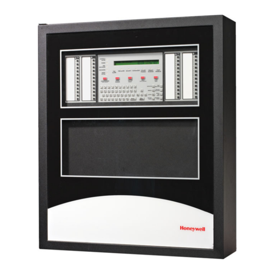
Honeywell XLS140 Installation Manual (88 pages)
FIRE ALARM CONTROL PANEL
Brand:
Honeywell
| Category:
Fire Alarms
| Size: 2.37 MB
Table of Contents
Table of Contents
5
Section 1: about this Manual
9
Standards and Other Documents
9
Supplemental Documentation
10
Cautions and Warnings
11
Section 2: System Overview
13
System Description
13
1: Standard Features
13
2: Options
13
3: System Limitations
14
System Components
14
1: Basic Equipment Required
14
2: Control Panel Circuit Board
15
3: Main Power Supply
15
4: Circuit Board Components
16
System Cabinets
18
Optional Devices
19
Intelligent Detectors
20
Addressable Modules
22
Annunciation Modules
23
Annunciators
23
1: Annunciators with 24- and 48-Point Capacity
24
2: Annunciator Fixed Modules
24
Peripheral Displays and Printers
24
Panel Circuit Modules
25
Voice Alarm System
26
Section 3: Installation
29
Preparing for Installation
29
1: Standards and Codes
29
Installation Checklist
30
Mounting a Cabinet
30
Laying out Equipment in Cabinet and Chassis
31
Installing the Control Panel
33
1: Control Panel Circuit Board & Keypad/Display Unit
33
2: Using XLS-NCA as Primary Display
35
3: Loop Expander Module
36
4: Network Control Module
37
5: Panel Circuit Modules and Other Option Boards
37
Connecting the Power Cables
39
1: Overview
39
2: Connecting the Control Panel to AC Power
39
3: Checking AC Power
40
4: Installing and Connecting the Batteries
40
5: APS-6R Auxiliary Power Supply Connections
41
6: External DC Power Output Connections
41
NAC Connections & Releasing Circuits
42
Output Relay Connections
42
Backup-Alarm Switches
43
Installing a Transmitter Module TM-4
43
UL Power-Limited Wiring Requirements
43
1: Labeling Modules and Circuits
44
Installing Panel Circuit Modules
44
1: Overview
44
2: Mounting Expander Boards
45
3: Connecting Ribbon Cables for a CAB-4 Series Backbox
45
4: Installing the Panel Circuit Modules
46
5: Connecting ICM-4RK and ICE-4 Modules
46
Power Supply Connections
47
Multiple Power Supplies
47
6: Field-Wiring the ICM-4RK and ICE-4 (NFPA Style y or Z)
48
7: Connecting CRM-4RK/CRE-4 Modules
49
Auxiliary Relay Module (ARM-4): Product-Specific Details
49
1: Overview
49
2: Installation
49
3: Field Wiring an Auxiliary Relay Module
50
Installing Remote Printers And/Or CRT
51
1: Custom Cable Fabrication
51
2: Installing and Configuring the PRN Series Printer
51
Connecting a Remote PRN Series Printer
51
Setting Printer Options
52
3: Installing and Configuring a Keltron Printer
52
Setting up the Keltron Printer
53
4: Installing and Configuring a CRT-2
53
Setting CRT-2 Parameters
54
5: Connecting a PC
55
6: Connecting Multiple Printers, Crts, or CRT/PRN Combination
55
Wiring a Signaling Line Circuit (SLC)
56
Section 4: Applications
59
Overview
59
Municipal Box (Auxiliary)
59
NFPA 72-1999 Central or Remote Station Fire Alarm System (Protected Premises Unit)
60
NFPA 72-1999 Proprietary Fire Alarm Systems
61
Fire/Security Applications
61
1: General Operation
61
2: Installing a Security Tamper Switch
62
3: Receiving Unit
62
4: Programming
63
5: Wiring for Proprietary Security Alarm Applications
63
Releasing Applications
64
1: Overview
64
2: Programming
64
3: Wiring
64
4: Connecting a Releasing Device to the Control Panel
65
5: Connecting a Releasing Device to the XLS-CM-N/TC810N1013 Module
66
6: Connecting an NBG-12LRA Agent Release-Abort Station
67
Section 5: Testing the System
69
Acceptance Test
69
Periodic Testing and Service
69
Operational Checks
69
Battery Checks and Maintenance
70
On-Board Memory-Backup Battery
70
Appendix A: Power Supply Calculations
71
A.1: Calculating AC Branch Circuit Current
71
AC Branch Circuit Installation
71
A.2: Calculating the System Current Draws
71
How to Use the Calculating Tables
71
A.2.1: Calculating the Maximum Secondary Power Fire Alarm Current Draw
74
A.3: Calculating the Battery Requirements
75
A.3.1: Calculating the Battery Capacity
75
A.3.2: Calculating the Battery Size
76
Appendix B: Electrical Specifications
77
B.1: Electrical Specifications
77
AC Power
77
Batteries
77
Signaling Line Circuit (SLC)
78
Notification Appliance Circuits & Releasing Circuits
78
Output Relays
78
Four-Wire Smoke Detector Power
78
Power Output
78
Operating Power: AC Branch Circuit
79
Operating Power: Secondary Power Source (Batteries)
79
B.2: Wire Requirements
79
Appendix C: Compatible Equipment
81
Honeywell and Notifier Equipment
81
System Sensor Equipment
82
Appendix D: Canadian Applications
83
D.1: Standalone Application
83
D.1.1: XLS140 with KDM-2
83
D.1.2: XLS140 with XLS-NCA
83
D.2: Local Network Application
83
D.3: Automatic Alarm Signal Silence
83
D.4: Annunciator Applications
83
D.5: Releasing Devices
83
Index
84
Advertisement
Advertisement
Related Products
Honeywell XLS80e
Honeywell XLS-REL
Honeywell XL 800 Series
Honeywell XL4600SM
Honeywell XL-2T
Honeywell Excel Web XL1000A
Honeywell Excel Web XL1000B
Honeywell HEATBUD XL HCE210 Series
Honeywell XNX-BTSE Series
Honeywell XPO 5PB
Honeywell Categories
Thermostat
Controller
Control Unit
Security Camera
Accessories
More Honeywell Manuals
Login
Sign In
OR
Sign in with Facebook
Sign in with Google
Upload manual
Upload from disk
Upload from URL