Sign In
Upload
Manuals
Brands
HP Manuals
Inverter
5334B
HP 5334B Manuals
Manuals and User Guides for HP 5334B. We have
2
HP 5334B manuals available for free PDF download: Service Manual, Operating And Programming Manual
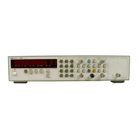
HP 5334B Service Manual (242 pages)
Universal Counter
Brand:
HP
| Category:
Cash Counter
| Size: 17.53 MB
Table of Contents
Table of Contents
5
Section 4 Performance Tests
11
Introduction
11
Equipment Required
11
Operational Verificationrerformance Test Record
11
Calibration Cycle
11
Test Procedures
11
Operational Verification Tests
12
Preliminary Procedure
12
Power-Up Self-Testmiagnostic Mode
13
Read Levels
14
Ratio A/B
15
Frequency
16
Input Signal Conditioning Check
16
Auto Trigger
19
Channel C (Option 030)
20
Performance Tests
22
Preliminary Procedure
22
Channel a Frequency Response and Sensitivity Test, 10 Hz-20 Mhz
27
Channel B Frequency Response and Sensitivity Test, 10 Hz-20 Mhz
30
Channel a Frequency Response and Sensitivity Test, 80 Mhz-100 Mhz
31
Period a Test
34
Pulse Width a Test
36
Time Interval a to B Test
38
Time Interval a to B Delay Test
39
Ratio A/B Test
40
Channel C Frequency Response and Sensitivity Test
44
HP 5334B Performance Test Record Card
47
HP-IB Verification Test
49
HP-IB Operational Verification Program Listing
56
Section 5 Adjustments
73
Introduction
73
Safety Considerations
73
Adjustable Components
74
Equipment Required
75
Factory-Selected Components
75
Related Adjustments
75
Power Supply Voltage Adjustment
75
Post-Repair Adjustments
75
Digital-To-Analog Converter (DAC) A/B Zero Adjustment
76
Digital-To-Analog Converter (DAC) A/B Gain Adjustment
77
10 Mhz Reference Oscillator Frequency Adjustment
79
Channel a Sensitivity Offset Adjustment
81
Channel a Sensitivity Adjust Setup
82
Channel B Sensitivity Offset Adjustment
83
Multiple-Register Counter (MRC) Input Adjustment, Ch a
85
Multiple-Register Counter (MRC) Input Adjustment, Ch B
87
Attenuator Adjustment
89
Channel C Peak Detector Adjustment, Option
91
Square Wave Overshoot
91
Section 6 Replaceable Parts
94
Introduction
94
Abbreviations
94
Reference Designations and Abbreviations
95
Replaceable Parts
96
Illustrated Parts Breakdown
96
Ordering Information
96
Section 7 Manual Changes
116
Introduction
116
Manual Changes
116
HP 5334B Backdating
116
Section 8 Service
121
Introduction
121
Safety Considerations -8-1
121
Circuit Descriptions
122
Troubleshooting -8-2
122
General
122
Signal Tracing
122
Signature Analysis
122
Recommended Test Equipment
123
Service Tools and Aids
123
Parts Locations
123
Adjustment and Test Point Locations
123
Service Aids on Printed Circuit Boards
123
Pozidriv Screwdrivers
123
Repairs
123
Cleaning Printed-Circuit Boards
123
Disassembly and Reassembly Procedures
124
Post-Repair Adjustments
124
Post-Service Product Safety Checks
124
Schematic Diagram Notes
124
Reference Designations
124
Identification Marks on Printed Circuit Boards
124
Schematic Diagram Notes
126
Logic Symbols
127
General Qualifying Symbols
127
Gate Symbols
129
Qualifying Symbols for Inputs and Outputs
129
Qualifying Symbols for Internal Connections
130
Symbols Inside the Outline
130
Qualifying Symbols for Inputs and Outputs
130
Symbols Inside the Outline
131
Dependency Notation
132
Summary of Dependency Notation
132
Control Blocks
133
Examples of Dependency Notation
133
Logic Device Notation Example
134
3-State Bidirectional Transceiver
134
Logic Levels
135
Theory of Operation
135
General
135
Executive Block Assembly
136
Measurement Block Assembly
136
Input Amplifier Block Assembly
136
DAC Block Assembly
136
Time Base Block Assembly
136
HP-IB Block Assembly
136
Power Supply Block Assembly
137
Channel C Input Block Assembly (Option 030)
137
MATE (CIIL) Block Assembly (Option 700)
137
Oven Oscillator Module (Option 010)
137
A2 Front Panel Board Assembly
137
Detailed Theory of Operation
137
Input Amplifier Block
137
Input Amplifier Block Circuit Description (Channel A)
138
Digital-To-Analog Converter (DAC) Block
140
Executive Block
142
Executive Block Circuit Description
143
Measurement Block
144
Measurement Block Circuit Description
144
Time Base Block
148
HP-IB Block
149
HP-IB Block Circuit Description
149
Power Supply Block
150
Power-Up RESET Circuit Description
150
Channel C Input Block (Option 030)
150
Power Supply Block Circuit Description
150
A2 Front Panel Board
151
MATE (CIIL) Block (Option 700)
152
A2 Front Panel Board Circuit Description
152
Oven Oscillator Module (Option 010)
153
MATE (CIIL) Block Circuit Description
153
Oven Oscillator Overall Block Diagram
155
Disassembly and Reassembly
157
Cover
158
A1 Main Board Removal and Installation
158
Troubleshooting
159
Electrostatic Discharge (ESD)
160
Signal Tracing
160
Power Supplies Resistance Checks
161
DC Voltages Check
161
Input Amplifier Troubleshooting
162
Digital-To-Analog Converter (DAC) Troubleshooting
168
Troubleshooting the DAC Switching Section
170
Measurement Block Troubleshooting
171
Executive Block Troubleshooting
173
Front Panel Block Troubleshooting
173
Time Base Troubleshooting
174
Troubleshooting Option 010 Oven Oscillator
174
Inspection
174
Special Parts Replacement Considerations
174
Special Test Connector
175
Temperature Set Resistor List
175
Special Test Connector
176
Types of Failures
177
Troubleshooting Tree
180
Oven Circuit Voltages
181
Oscillator Section Normal Voltages
183
Output Amplitude Adjustment Setup
187
HP-IB Block Signatures
199
PI0 A1 Main Board Input Amplifier Block Schematic Diagram
216
PI0 A1 Main Board DAC Block Schematic Diagram
219
PI0 A1 Main Board Executive/Measurement Block Schematic Diagram
222
PI0 A1 Main Board HP-IB Block Schematic Diagram
225
PI0 A1 Main Board Option 700 MATE Block Schematic Diagram
231
Advertisement
HP 5334B Operating And Programming Manual (171 pages)
Universal counter
Brand:
HP
| Category:
Counter
| Size: 8.19 MB
Advertisement
Related Products
HP 5314A
HP 5316B
HP HP 5347A
HP HP 5348A
HP 5334A
HP 59307A VHF
HP 581A
HP 580A
HP 5065A
HP 54200A
HP Categories
Desktop
Laptop
Server
Monitor
Switch
More HP Manuals
Login
Sign In
OR
Sign in with Facebook
Sign in with Google
Upload manual
Upload from disk
Upload from URL