Sign In
Upload
Manuals
Brands
HP Manuals
Pulse Generator
8112A
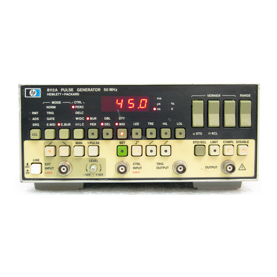
User Manuals: HP 8112A Pulse Generator
Manuals and User Guides for HP 8112A Pulse Generator. We have
3
HP 8112A Pulse Generator manuals available for free PDF download: Operating, Programming And Servicing Manual
HP 8112A Operating, Programming And Servicing Manual (406 pages)
50 MHz Programmable Pulse Generator
Brand:
HP
| Category:
Portable Generator
| Size: 14.67 MB
Table of Contents
Table of Contents
7
Figures
19
General
25
Instruments Covered by this Manual
25
Introduction
25
HP 8112A Options
26
Instrument Description
26
Accessories
27
Recommended Test Equipment
28
Common Specifications
29
Specifications Introduction
29
Timing Parameters
29
Delay (DEL) (after Trigger Out)
30
Duty Cycle (DTY)
30
Linear Transitions (between 10% and 90% Amplitude)
30
Period (PER)
30
Pulse Width (WID)
30
High Level (HIL)
31
Low Level (LOL)
31
Operating Characteristics
31
Output Parameters
31
Control Modes
32
External Burst
32
External Width
32
Gate
32
High-Level Control
32
Normal
32
Period, Delay, Double Pulse and Width Control
32
Settling Time (Within 5% of Final Value)
32
Trigger
32
Trigger Modes
32
Control Input
33
Cosine Transitions
33
External Input
33
Fixed Transitions
33
Inputs and Outputs
33
Linear Transitions
33
Output Modes
33
Trigger Output
33
Additional Features
34
Main Output
34
Dimensions
35
Environmental
35
General Characteristics
35
Power Supply
35
Recalibration Period
35
Weight
35
Initial Inspection
37
Installation Introduction
37
Safety Considerations
37
Power Requirements and Line Voltage Selection
38
Power Cable
39
HB-IB Connector
41
HP-IB Connector
41
HP-IB Logic Levels
41
Claims and Repackaging
42
Humidity
42
Instrument Cooling
42
Operating Environment
42
Temperature
42
Return Shipment to HP
43
Storage and Shipment
43
Introduction
45
Operating
45
Switching on
45
Error Codes
47
Standard Parameter Set
48
Mode Selection
49
Selecting Trigger Mode
49
Trigger Mode Controls
49
Controlling the External Trigger
50
External Trigger Controls
50
Trigger Level
50
Trigger Output
50
Trigger Slope
50
Control Input
51
Relationship between Control Input Voltage and
51
Selecting Control Mode
51
Delay Control (DELC)
52
High Level Control (HILC)
52
Mode Selection
52
Period Control (PERC)
52
Width Control (WIDC)
52
High Level Control Capabilities
53
Setting Transition Modes
54
Up and Down-Ranging, Using the VERNIER Keys
55
Up and Down-Ranging Using the RANGE Key
56
Adjustment
57
Parameter Controls
57
Period/Burst Key
57
Selection
57
Setting Parameters
57
Delay/Double Key
58
High and Low Level Keys (HIL) M
58
Leading and Trailing Edge Keys B (TRE)
58
Per
58
Width/Duty Key
58
Store and Recall Key (M)
59
Complement Output (S)
60
Disabled Output (DISABLE)
60
Limited Output M
60
Selecting Output Mode
60
Fuse
62
Hold in
62
HP-IB Connector
62
Marker Output
62
O U T
62
Rear Panel
62
Introduction
63
Normal Mode
63
Operating Examples
63
Triggering Examples
63
Trig Mode
64
Typical Signals in Trigger Mode
64
Gate Mode
65
Typical Signals in Gate Mode
65
External Width Mode
66
Typical Signals in External Width Mode
66
External Burst Mode
67
Typical Signals in External Burst Mode
67
Analog Applications
68
Applications
68
Cosine Shaped Transition Modes (Gaussian)
68
Fixed Transition Mode
68
Linear Transition Mode
68
Cosine Shaped Transition Mode
69
Digital Applications
69
Fixed Transition Mode
69
Linear Variable Transition Mode
69
General
71
Programming
71
Setting the HP-IB Address
71
Local, Remote and Local Lockout
72
Abbreviations Used in this Document
73
Terminators
73
Example
74
Examples
74
Multiple Commands
74
Programming
74
Example
76
Selecting Control Modes
76
Selecting Trigger Modes
76
Standard Trigger Modes
76
Trigger Control
76
Example
77
Selecting Output Waveform Mode
77
Setting Parameters
77
Timing Parameters
77
Burst Parameter
78
Example
78
Level Parameters
78
Vernier
78
Example
79
Excessive Slope Calculation
79
Range Change
79
Stored Parameters
79
Example
80
Reading Parameters
80
Example
81
Output Controls
81
Reading the Current Settings
81
Selecting Output Modes
81
Answer
82
Data Transmission Time
82
Example
82
Implementation Time
82
Send
82
Timing
82
Error, Fault and Status Reporting
83
Hardware Settling Time
83
HP-IB Status Byte
83
Limit Error (Bit 0)
84
Slope Error (Bit 3)
85
Syntax Error (Bit 2)
85
Timing Error (Bit 1)
85
Duty Cycle Error (Bit 4)
86
Example
86
Buffer Not Empty (Bit 7)
87
Input Error (Bit 5)
87
Service Request (Bit 6)
87
Dcl Sdc
88
Get
88
HP-IB Universal Commands
88
Example
89
Hints for Solving Problems that Might Occur
89
Reading the Status Byte
89
Possible Problem with SPOLL
90
Terminators
90
Interrogate Timing
91
Common Task Examples
93
General Examples
93
Introduction
93
Programming Examples
93
Testing Communication
94
Performing Self-Test
96
Using the Buffer Not Empty Flag
98
Common Task Examples
100
Program DEL-WID
100
Comments
102
Important Program Lines
102
Initialization Section
102
Main Section
102
Program SPOLL-2
102
Purpose
102
Comments
104
Main Section
104
Purpose
104
Setup Section (Lines 110 - 120)
104
Subroutine Section
104
The Service-Srq Subroutine
104
Comments
105
Error-Demo
105
Purpose
105
Comments
108
Learn String (Delay Mode Active)
108
Learn String (Double Mode Active)
108
Lrn-Demo
108
Purpose
108
Comments
110
Interrog
110
Program Listing
110
Purpose
110
Screen Dump of the Results Printed When Running the Program INTERROG
110
Introduction
113
Testing Performance
113
Test Equipment
114
Equipment
115
Period Performance Test
115
Procedure
115
Specifications
115
Test Setup
115
Delay Performance Test
116
Equipment
116
Specifications
116
Delay Performance Test
117
Procedure
117
Test Setup
117
Double Pulse Performance Test
118
Equipment
118
Specifications
118
Test Setup 1
118
Test Setup 2
119
Pulse Width Performance Test
120
Specifications
120
Equipment
121
Procedure
121
Pulse Width Performance Test
121
Test Setup 1
121
Test Setup 2
121
Constant Duty Cycle Performance Test
122
Specifications
122
Equipment
123
Procedure
123
Test Setup
123
Equipment
124
Output Levels Performance Test
124
Specifications (Values in Parenthesis into Open Circuit)
124
Equipment
126
Procedure
126
Specifications
126
Test Setup
126
Transition Time Performance Test
126
Transition Times Performance Test
126
Slow Transitions
127
Transitions
127
Equipment
128
Procedure 1
128
Pulse Performance Test
128
Specifications
128
Test Setup
128
Characteristics
130
Pulse Performance Characteristics
130
Trigger,Gate,E.width and E.burst Verification Test
130
Equipment
131
Procedure
131
Test Setup
131
Trigger, Gate,E.wid & E.BUR Verification Test
131
Characteristics
133
Output Mode Verification Test
133
Test Setup 1
133
Test Setup 2
133
Equipment
134
Procedure
134
Equipment
135
Period Control Verification Test
135
Test Setup
135
Characteristics
136
Delay Control Verification Test
136
Equipment
136
Procedure
136
Correct Delay Control
137
Delay Control Verification Test
137
Procedure
137
Test Setup
137
Characteristics
138
Equipment
138
Width Control Verification Test
138
Characteristics
139
Equipment
139
High-Level Control Verification Test
139
Procedure
139
High-Level Control Verification Test
140
Procedure
140
Test Setup
140
Characteristics
141
Store and Recall Function Test
141
Equipment
142
HP-IB Verification Test
142
Procedure
142
Test Setup
142
PERFORMANCE TEST RECORD Page 2 of 8
146
Adjustment Procedures
153
Introduction
153
Equipment
156
Power Supplies
156
Procedure
156
Test Preparation
156
Equipment
157
Minimum Pulse Droop
157
Pre Adjustments
157
Procedure
157
Amplitude/Offset
158
Normal/Complement
158
Equipment
159
Overshoot & Transition Time Adjustment
159
Procedure
159
Equipment
162
Period
162
Procedure
162
Timing
162
Delay (Double Pulse)
163
Equipment
165
Width Adjustment
165
Equipment
167
Fixed Amplitude
167
Procedure
167
Shaper and Offset Adjustments
167
Linear Amplitude
168
Gauss Amplitude
169
Offset
169
Hil C
170
Equipment
171
Procedure
171
Slope
171
Introduction to Servicing
177
Safety Check
177
Safety Considerations
177
General
179
Instrument Overview and Troubleshooting Guide
181
Theory of Operation
181
Trouble Shooting
183
El1
185
El2
185
El3
185
El4
185
Eol
185
Key Jammed
185
RAM Test
185
Timing Tests
185
Output Amplifier Tests
187
Overall Tests, Dynamic
187
Overall Tests, Static
187
Amplitude Tests
189
Burst Tests
189
Shaper Output State Test
189
Bridge Rectifiers and Regulators
191
Line Voltage Selector and Transformer
191
Servicing the Power Supply
191
Theory of Operation
191
Voltage and Current Sensing Circuits
191
Power-Down Detection
193
Re-Fitting the Fan
199
Removing the Fan
199
Troubleshooting the Power Supply
199
Servicing the Timing and Slope Generators
201
Theory of Operation
201
Trigger Input
201
Trigger Mode
201
Address Decoder
202
Control Input Circuits
202
Mode and Range Decoders
202
Timing IC
202
Timing Generation
203
RATE Mode
204
TIME Mode
204
Error Output
205
Outputs
205
Period, Delay and Width Generation
205
Delay Generator
206
Width Generator
206
Fixed Transition
207
Linear and Gaussian Transitions
207
Slope Generation
207
Current Sources
208
Error Feedback
208
Range Switches
208
Reference Circuit
208
Address Decoder
215
Troubleshooting
215
Control Mode Selection
217
Period Generator
218
Delay Generator
220
Width Generator 1
221
Slope Generator
223
Range Decoder
224
Bus Latch
225
Introduction
225
Servicing the Shaper and Output Amplifier
225
Shaper IC
225
Theory of Operation
225
Wave Forming
226
Current Mirror
227
Output Mode
227
Shaper Output
227
Pre-Attenuator
228
Signal Output Amplifier
228
Input
229
Level Check Circuit
230
Output
230
Trigger Output Amplifier
230
Voltage Gain
230
Shaper IC Inputs
235
Troubleshooting
235
Output Controls
237
Pre-Attenuator and Output Attenuator Control Signals
237
Shaper IC Amplitude-Vernier Control-Voltage
237
Shaper IC Current-Mirror
237
Shaper IC Reference Current
237
Transition Mode and Output Control Signals
237
Offset-Vernier Control-Voltage
238
Output Amplifier
238
Advertisement
HP 8112A Operating, Programming And Servicing Manual (406 pages)
50 MHz Programmable Pulse Generator
Brand:
HP
| Category:
Pulse Generator
| Size: 5.46 MB
Table of Contents
Table of Contents
7
Figures
19
General
25
Instruments Covered by this Manual
25
Introduction
25
Serial Number Plate ( FRG )
25
HP 8112A Options
26
Instrument Description
26
Accessories
27
Recommended Test Equipment
28
Common Specifications
29
Specifications Introduction
29
Timing Parameters
29
Delay (DEL) (after Trigger out )
30
Double Pulse {DBL) {Interval between Leading Edges)
30
Duty Cycle (DTY)
30
Linear Transitions (between 10% and 90% Amplitude)
30
Period (PER)
30
Pulse Width {WID)
30
High Level (HIL)
31
Low Level (LOL)
31
Operating Characteristics
31
Output Parameters
31
Trigger Modes
32
Main Output
34
General Characteristics
35
Line Voltage Selector Switches
38
Power Requirements and Line Voltage Selection
38
Power Cables Plug Identification
39
HP-IB Connector
41
Operating Environment
42
Storage and Shipment
43
External Trigger Controls
45
Switching on
46
Normal
48
Standard Parameter Set
48
Gate
49
Selecting Trigger Mode
49
Trigger
49
Trigger Mode Controls
49
Control Mode Controls
51
Relationship between Control Input Voltage and
51
Selecting Control Mode
51
Mode Selection . ( )
52
High Level Control Capabilities
53
LEE and TRE Ranges
55
Transition Ranges
55
Ranging Examples
56
Up and Down-Ranging Using the RANGE Key
56
Parameter Controls
57
Width/Duty Key
58
Rear Panel
62
Introduction
63
Typical Output in Normal Mode
63
Trigger Slope
66
Typical Signals in External Width Mode
66
Typical Signals in External Burst Mode
67
Capacitance Circuit
68
Digital Applications
69
Trigger Level
72
Terminators
73
Output Controls
81
Status Reporting
83
Interrogate Timing
91
Introduction
93
Testing Communication
94
Using the Buffer Not Empty Flag
98
Common Task Examples
100
Program SPOLL_2
102
Intr_2
104
Error_Demo
105
Learn String (Double Mode Active)
108
Interrog
110
Test Equipment
114
Specifi C Ations
116
Delay Performance Test
117
Gate Mode
117
Double Pulse Performance Test
118
Double Pulse Performance Test
119
Test Setup 2
119
Pulse Width Performance Test
120
Equipment
121
Pulse Width Performance Test
121
Constant Duty Cycle Performance Test
122
Duty Cycle Performance Test
123
Fast Transitions
127
Equipment
128
Pulse Performance Test
128
Specifi C Ations
129
External Burst
130
External Width
130
Control Modes
131
Characteristics
133
Output Mode Verification Test
133
Output Mode Verification Test
134
Test Setup 2
134
Period Control Verification Test
135
Delay Control Verification Test
136
Procedure
136
Correct Delay Control
137
Test Setup
137
HP-IB Verification Test
138
Width Control Verification Test
138
High-Level Control
139
Settling Time (Within 5% of Final Value)
139
High-Level Control Verification Test
140
Correct Delay Control
141
Store and Recall Function Test
141
Performance Test Record
145
Output Modes
151
Store and Recall
152
Procedure
153
Complement
155
Access to the HP 8 1 1 2A for Adjustments
156
Test Equipment
156
Disable
157
Limit
157
Pre Adjustments Setup
157
Trigger Output
158
Overshoot Transition Time Adjustment
159
Timing
162
Equipment
165
Low Pass Filter
169
Test Setup
171
Safety Check
177
General
179
Control Input
202
Output Amplifier
238
Output Levels Performance Test
389
Declaration of Conformity
396
HP 8112A Operating, Programming And Servicing Manual (112 pages)
50 MHz programmable Pulse Generator
Brand:
HP
| Category:
Pulse Generator
| Size: 2.84 MB
Advertisement
Advertisement
Related Products
HP 8116As
HP 8116A
HP 81101A
HP 81110A
HP 81104A
HP 8110A
HP 8133A
HP 8012A
HP ProCurve 8116fl
HP 8114A
HP Categories
Desktop
Laptop
Server
Monitor
Switch
More HP Manuals
Login
Sign In
OR
Sign in with Facebook
Sign in with Google
Upload manual
Upload from disk
Upload from URL