Sign In
Upload
Manuals
Brands
HP Manuals
Control Unit
E3456A
User Manuals: HP E3456A Control Unit
Manuals and User Guides for HP E3456A Control Unit. We have
1
HP E3456A Control Unit manual available for free PDF download: User Manual
HP E3456A User Manual (171 pages)
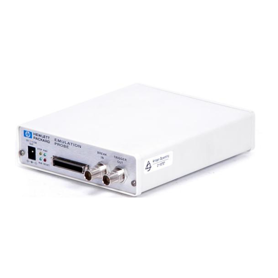
Emulation for the PowerPC MPC500
Brand:
HP
| Category:
Control Unit
| Size: 4.39 MB
Table of Contents
Emulation for the Powerpc MPC500-At a Glance
4
Emulation Module
5
Emulation Probe
5
In this Book
6
Table of Contents
7
1 Installing the Emulation Probe
15
Overview of Installation and Setup
16
Equipment and Requirements
18
Supplied Equipment and Software
18
Additional Equipment and Software Required
19
Other Optional Equipment
20
Powering-On and Powering-Off the Emulation Probe
21
To Power on the System
21
To Power off the System
21
To Connect the Emulation Probe to a Power Source
21
Connecting the Emulation Probe to a LAN
23
To Get the IP and Gateway Addresses
24
To Configure LAN Parameters Using the Built-In Terminal Interface
25
To Configure LAN Parameters Using BOOTP
28
To Set the 10BASE-T Configuration Switches
30
To Verify LAN Communications
31
Solving LAN Communication Problems
33
If You Cannot Verify LAN Communication
33
If You Have LAN Connection Problems
34
If the "POL" LED Is Lit
35
If It Takes a Long Time to Connect to the Network
35
Connecting a Terminal to the Emulation Probe's Serial Port
36
To Set the Serial Configuration Switches
36
To Connect a Serial Cable
37
To Verify Serial Communications
38
Solving Serial Communication Problems
40
If You Cannot Verify RS-232 Communication
40
If You Have RS-232 Connection Problems with the MS Windows Terminal Program
40
Updating Emulation Probe Firmware
42
To Display Current Firmware Version Information
42
To Update Firmware for an Emulation Probe
42
2 Installing the Emulation Module
45
Overview of Installation and Setup
46
Equipment and Requirements
48
Supplied Equipment and Software
48
Additional Equipment and Software Required
49
Installing into a Logic Analysis System
50
To Install in a HP 16700A-Series Logic Analysis System
50
To Install in a HP 16600A-Series Logic Analysis System
53
To Test the Emulation Module
55
Installing Software
56
To Install Software from CD-ROM
56
Updating Emulation Module Firmware
58
To Display Current Firmware Version Information
58
To Update Firmware Using the Emulation Control Interface
58
To Update Firmware Using the Setup Assistant
59
Preparing for a Debugger
61
To Connect the Logic Analysis System to the LAN
61
To Change the Port Number of an Emulation Module
62
To Verify LAN Communication with the Emulation Module
63
3 Connecting to a Target System
65
Designing the Target System for an Emulation Probe/Module
66
Target System Requirements
66
Debug Port Connection
66
SYPCR Register
69
On-Chip Flash Support
70
Fast Download
70
Making the Target System Connection
71
To Connect to a Target System Debug Port
71
To Connect to the Analysis Probe
73
To Verify Communication with the Target System
75
4 Configuring the Emulation Probe/Module
77
Entering Emulation Probe/Module Commands
79
To Use the Emulation Control Interface
79
To Use the Built-In Command Interface
81
To Use a Debugger Interface
82
Setting the Mpc5Xx Configuration Options
83
To Configure the Processor Type
83
To Configure the Processor Clock Speed
84
To Configure the Debug Port Connection Type
85
To Configure the Reset Configuration Word Source
86
To Configure the "Break In" Type
86
To Configure the Trigger out BNC
87
To Configure the Trigger in BNC
87
To Configure the BNC Break Type
88
To Configure Restriction to Real-Time Runs
88
Testing the Emulation Probe/Module and the Target System
89
To Test Memory Accesses
89
To Test by Running a Program
89
5 Using Debuggers
91
Setting up Debugger Software
94
To Change the Port Number of an Emulation Probe/Module
95
To View Logic Analysis System Windows Next to the Debugger
95
Using the Green Hills Debugger
97
To Get Started
97
To Configure Using an Initialization Script
100
To Perform Common Debugger Tasks
101
To Send Commands to the Emulation Probe/Module
102
To View Commands Sent by MULTI to the Emulation Probe/Module
102
To Reinitialize the System
103
To Disconnect from the Emulation Probe/Module
103
Error Conditions
103
Using the Microtec Research Debugger
105
To Get Started
105
To Configure the Emulation Probe/Module Using an INCLUDE File
108
To Perform Common Debugger Tasks
108
To Send Commands to the Emulation Probe/Module
109
To View Commands Sent by XRAY
109
To Disconnect from the Emulation Probe/Module and Target
110
Error Conditions
110
Using the Software Development Systems Debugger
112
To Get Started
113
To Send Commands to the Emulation Probe/Module
115
Download Performance
116
On-Chip Breakpoints and Debugging ROM Code
117
Error Conditions
117
6 Solving Problems
119
Troubleshooting Guide
121
Status Lights
123
Emulation Probe Status Lights
123
Emulation Module Status Lights
126
Built-In Commands
127
To Telnet to the Emulation Probe/Module
127
To Use the Built-In Commands
128
Solving Target System Problems
130
What to Check First
130
To Interpret the Initial Prompt
131
If Interrupts Are Non-Recoverable
132
If Hardware Breakpoints Have no Effect
133
If the Target Resets Itself
134
If Running from Reset Causes Problems
134
If You See the "!ASYNC_STAT 173!" Error Message
135
If There Are Problems with the Debug Port Signals
135
To Test the Target System
135
Solving Emulation Probe Problems
137
To Run the Power up Self Test
137
To Run the Performance Verification Tests
139
To Run the Performance Verification Tests Using the Logic Analysis System
140
To Run Complete Performance Verification Tests for an Emulation Probe
140
If a Performance Verification Test Fails
142
Solving Emulation Module Problems
145
To Run the Performance Verification Tests Using the Logic Analysis System
145
To Run Complete Performance Verification Tests Using a Telnet Connection
146
If a Performance Verification Test Fails
147
7 Specifications and Characteristics
149
Emulation Probe Electrical Specifications
150
Emulation Probe Operating/Environmental Characteristics
151
Emulation Probe/Module Electrical Characteristics
152
Emulation Module Operating Characteristics
152
8 Service Information
153
To Return a Part to Hewlett-Packard for Service
154
To Get Replacement Parts
154
To Clean the Instrument
156
Advertisement
Advertisement
Related Products
HP E1407A
HP E1403C
HP E1509
HP E1413
HP HP E1361A
HP E Series
HP E1419A
HP E2261A
HP E1364A
HP E1361A 4X4
HP Categories
Desktop
Laptop
Server
Monitor
Switch
More HP Manuals
Login
Sign In
OR
Sign in with Facebook
Sign in with Google
Upload manual
Upload from disk
Upload from URL