Sign In
Upload
Manuals
Brands
IBM Manuals
Storage
4002-C4A
IBM 4002-C4A Manuals
Manuals and User Guides for IBM 4002-C4A. We have
2
IBM 4002-C4A manuals available for free PDF download: Installation And User Manual
IBM 4002-C4A Installation And User Manual (98 pages)
Brand:
IBM
| Category:
Storage
| Size: 1.27 MB
Table of Contents
Table of Contents
5
Figures
9
Tables
11
Preface
13
Safety Notices
13
Safety Notices and Labels
13
Attention Notices
14
Caution Notices
14
Notes
14
Danger Notices
15
Safety Labels
18
Rack Installation
20
Rack Safety
20
Product Recycling and Disposal
21
Rack Relocation (19" Rack)
21
Product Documents
22
Software Documents
22
Comparable IBM and Brocade Products
23
Accessibility Features
24
Accessibility Features for the IBM Ethernet Switch C-Series
24
IBM and Accessibility
24
Keyboard Navigation
24
Related Accessibility Information
24
Vendor Software
24
Getting Help
25
How to Send Your Comments
25
Taiwan Contact Information
25
Chapter 1. About this Guide
27
Audience
27
Nomenclature
27
Summary of Changes
27
Chapter 2. Product Overview
29
Introduction
29
Product Overview
29
Software Features
30
Hardware Features
30
B24C (Copper) (4002-C2A / 4002AC2)
30
B24C (Fiber) (4002-C2B / 4002BC2)
30
B24C (Copper) (4002-C2A / 4002AC2) Shown
30
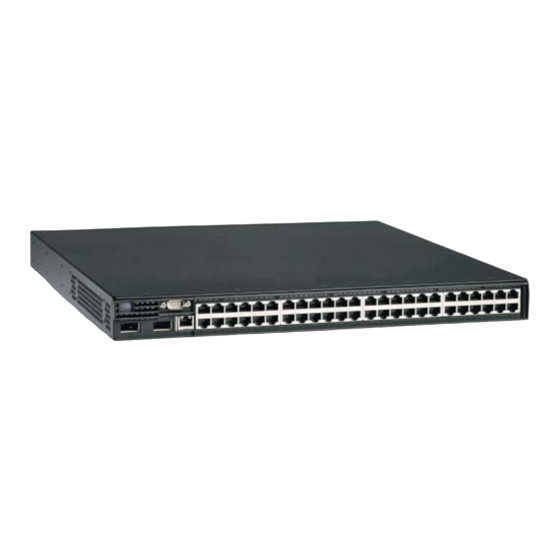
B48C (Copper) (4002-C4A / 4002AC4)
31
B50C (Copper) (4002-C5A / 4002AC5)
31
B48C (Fiber) (4002-C4B / 4002BC4)
31
B24C (Fiber) (4002-C2B / 4002BC2) Shown
31
B50C (Fiber) (4002-C5B / 4002BC5)
32
Control Features
32
Serial Management Interface (Console Port)
32
Leds for Ports
32
Network Interfaces
33
LED Status Descriptions for 10/100/1000 Mbe RJ45 Network Interface Ports
33
LED Status Descriptions for 10 Gbe XFP
33
Supported Optics
34
Port Regions
34
Power Supplies
35
AC Power Supplies
35
About Redundant Power Supplies and Power Supply Failure
36
Cooling System and Fans
36
AC Power Supply
36
Copyright IBM Corp. 2009
37
Chapter 3. Installation
37
Unpacking a System
37
Package Contents
37
General Requirements
37
Summary of Installation Tasks
37
Installation Precautions
39
Lifting Precautions
39
Power Precautions
39
Preparing the Installation Site
39
Cabling Infrastructure
40
Installation Location
40
Installing a Redundant Power Supply
40
Installing an AC Power Supply
40
AC Power Supply
41
Installing the Device
42
Desktop Installation
42
Rack Mount Installation
42
Forward Rack Mount Position
42
Front Rack Mount Position
43
Inch Offset Rack Mount Position
44
MID Rack Mount Position
45
Reverse Rack Mount Position
46
Installation Steps
46
Powering on the System
47
Installing the Switch in a Rack
47
Verifying Proper Operation
48
Observing the Power Status Leds
48
Leds for Power and Fans
48
LED for Power Supply
49
Attaching a PC or Terminal
49
LED Descriptions for LED on AC Power
49
Chapter 4. Connecting a C-Series Switch to a Network Device
51
Assigning Permanent Passwords
51
Configuring IP Addresses
52
Support of Sub-Net Masks
52
Assigning IP Addresses
52
Assigning an IP Address to a Management Interface
53
Assigning an IP Address to an Interface, Virtual Interface, or Loopback
53
Enabling and Disabling the Interfaces
54
Enabling Telnet
54
Understanding How the Management Port Functions
55
Connecting a C-Series Switch
55
Installing a SFP or XFP Transceiver
55
Cabling a Fiber Optic SFP or XFP Transceiver
56
Cleaning Fiber Optic SFP or XFP Transceivers
56
Chapter 5. Getting Familiar with C-Series Command Line Interface (CLI)
57
Logging on through the CLI
57
Online Help
57
Command Completion
58
Scroll Control
58
Line Editing Commands
58
Searching and Filtering Output from CLI Commands
59
Searching and Filtering Output from Show Commands
59
Displaying Lines Containing a Specified String
59
Displaying Lines that Do Not Contain a Specified String
59
CLI Line Editing Commands
59
Displaying Lines Starting with a Specified String
60
Searching and Filtering Output at the -More-Prompt
60
Using Special Characters in Regular Expressions
61
Special Characters for Regular Expressions
61
Chapter 6. Maintaining the Hardware
65
Hardware Maintenance Schedule
65
Replacing a Power Supply
65
Installation Precautions and Warnings
65
Determining Which Power Supply Failed
65
AC Power Supplies
66
Removing an AC Power Supply
66
Installing an AC Power Supply
66
Verifying Proper Operation
67
Displaying the Status of the Power Supplies
67
Power Supply Locking Screws
67
Installing or Replacing a 2-Port 10-Gigabit Ethernet Module
68
Removing a 2-Port 10-Gigabit Ethernet Module
68
Installing a 2-Port 10-Gigabit Ethernet Module
68
Replacing the Fan Tray
68
Replacing a SFP or XFP Transceiver
69
Removing a SFP or XFP Transceiver
69
Replacing the Fan Tray
69
Installing a New SFP or XFP Transceiver
70
Cabling a Fiber SFP or XFP Transceiver
71
Cleaning the Fiber Optic Connectors
71
Removing the Battery
71
Example Time Keeper Cover Location, B48C (C)
72
Chapter 7. Upgrading Software Images and Configuration Files
73
Upgrading the Software
73
Images and Procedures Required
73
Software Image Files
73
Description of the Software Images Required
74
Upgrading the Multi-Service Ironware Software
74
Description of Software Images
74
Displaying Flash Memory and Version Information
75
Displaying Flash Information
75
Displaying Version Information
76
Code Flash and Boot Flash Information
76
Backing up the Current Software Images
77
Virtual Interface Module
77
Upgrading the Multi-Service Ironware Image
77
Upgrading the Device's Monitor and Boot Images
78
Loading and Saving Configuration Files
78
Command Syntax for Upgrading Monitor and Boot Images on the Switch
78
Replacing the Startup Configuration with the Running Configuration
79
Replacing the Running Configuration with the Startup Configuration
79
Copying a Configuration File to or from a TFTP Server
79
Making Local Copies of the Startup Configuration File
80
Dynamic Configuration Loading
80
Usage Considerations
80
Preparing the Configuration File
80
Loading the Configuration Information into the Running-Config
82
Using SNMP to Save and Load Configuration Information
82
Erasing Image and Configuration Files
83
Scheduling a System Reload
83
Reloading at a Specific Time
83
Reloading after a Specific Amount of Time
84
Diagnostic Error Codes and Remedies for TFTP Transfers
84
Error Codes, Messages, Explanations and
85
Appendix. Hardware Specifications
87
Hardware Specifications
87
Power Specifications
87
Maximum Power Calculations at 100-240 VAC
87
Physical Dimensions
88
Operating Environment
88
Storage Environment
88
Cooling
88
Physical Dimensions of the Switches
88
C-Series Switches Operating Environment
88
C-Series Switches Storage Environment
88
Port Specifications
89
Console Port Pin Assignments
89
Console Port Pin and Signalling Details
89
Management Port Pin Assignments
90
Console Port Pin Assignments Showing Cable Connection Options to a Terminal or PC
90
Notices
91
Trademarks
92
Electronic Emission Notices
92
Federal Communications Commission (FCC) Class a Statement
92
Industry Canada Class a Emission Compliance Statement
93
Avis de Conformité À la Réglementation D'industrie Canada
93
European Union (EU) Electromagnetic Compatibility Directive
93
Germany Electromagnetic Compatibility Directive
93
People's Republic of China Class a Electronic Emission Statement
94
Japan VCCI Class a ITE Electronic Emission Statement
94
Korea Class a Electronic Emission Statement
94
Index
95
Advertisement
IBM 4002-C4A Installation And User Manual (94 pages)
Brand:
IBM
| Category:
Switch
| Size: 2.52 MB
Table of Contents
Table of Contents
5
Figures
9
Tables
11
Preface
13
Safety Notices
13
Safety Notices and Labels
13
Attention Notices
14
Caution Notices
14
Notes
14
Danger Notices
15
Safety Labels
18
Rack Installation
20
Rack Safety
20
Product Recycling and Disposal
21
Rack Relocation (19" Rack)
21
Product Documents
22
Software Documents
22
Getting Help
23
Taiwan Contact Information
23
How to Send Your Comments
24
Chapter 1. About this Guide
25
Audience
25
Nomenclature
25
Chapter 2. Product Overview
27
Introduction
27
Product Overview
27
B50C (4002-C5A) Copper Ethernet Switch
27
Software Features
28
Hardware Features
28
B48C (4002-C4A) Copper
28
B50C (4002-C5A) Copper
28
B48C (4002-C4A) Copper Ethernet Switch
28
B48C (4002-C4B) Fiber
29
B50C (4002-C5B) Fiber
29
Control Features
29
Serial Management Interface (Console Port)
29
Leds for Ports
29
B48C and B50C Network Interfaces
30
Supported Optics
30
Port Regions
31
Power Supplies
31
AC Power Supplies
32
About Redundant Power Supplies and Power Supply Failure
32
Cooling System and Fans
32
AC Power Supply
32
Chapter 3. Installation
33
Unpacking a System
33
Package Contents
33
General Requirements
33
Summary of Installation Tasks
34
Installation Precautions
35
Lifting Precautions
35
Power Precautions
35
Preparing the Installation Site
36
Cabling Infrastructure
36
Installation Location
36
Installing a Redundant Power Supply
36
Installing an AC Power Supply
36
AC Power Supply
37
Installing the Device
38
Desktop Installation
38
Rack Mount Installation
38
Forward Rack Mount Position
38
Reverse Rack Mount Position
42
Installation Steps
42
Powering on the System
43
Verifying Proper Operation
44
Observing the Power Status Leds
44
Leds for Power and Fans
44
Attaching a PC or Terminal
45
Leds for Power
45
Chapter 4. Connecting a C-Series Switch to a Network Device
47
Assigning Permanent Passwords
47
Configuring IP Addresses
48
Support of Sub-Net Masks
48
Assigning IP Addresses
48
Assigning an IP Address to a Management Interface
49
Assigning an IP Address to an Interface, Virtual Interface, or Loopback
49
Enabling and Disabling the Interfaces
50
Understanding How the Management Port Functions
51
Connecting a C-Series Switch
51
Installing a Fiber-Optic Module
51
Cabling a Fiber-Optic Module
52
Cleaning Fiber-Optic Modules
52
Chapter 5. Getting Familiar with C-Series Command Line Interface (CLI)
53
Logging on through the CLI
53
Online Help
53
Command Completion
53
Scroll Control
54
Line Editing Commands
54
Searching and Filtering Output from CLI Commands
55
Searching and Filtering Output from Show Commands
55
Displaying Lines Containing a Specified String
55
Displaying Lines that Do Not Contain a Specified String
55
Displaying Lines Starting with a Specified String
56
Searching and Filtering Output at the -More-Prompt
56
Using Special Characters in Regular Expressions
57
Chapter 6. Maintaining the Hardware
61
Hardware Maintenance Schedule
61
Replacing a Power Supply
61
Installation Precautions and Warnings
61
Determining Which Power Supply Failed
61
AC Power Supplies
62
Removing an AC Power Supply
62
Installing an AC Power Supply
62
Verifying Proper Operation
63
Power Supply Locking Screws
63
Displaying the Status of the Power Supplies
64
Replacing a Fiber Optic Module
65
Removing a Fiber Optic Module
65
Installing a New Fiber Optic Module
66
Cabling a Fiber Optic Module
66
Cleaning the Fiber Optic Connectors
66
Upgrading the Software
67
Chapter 7. Upgrading Software Images and Configuration Files
69
Images and Procedures Required
69
Software Image Files
69
Description of the Software Images Required
70
Upgrading the Multi-Service Ironware Software
70
Displaying Flash Memory and Version Information
70
Displaying Flash Information
71
Displaying Version Information
72
Backing up the Current Software Images
73
Virtual Interface Module
73
Upgrading the Multi-Service Ironware Image
73
Upgrading the Device's Monitor and Boot Images
74
Loading and Saving Configuration Files
74
Command Syntax for Upgrading Monitor and Boot Images on the Switch
74
Replacing the Startup Configuration with the Running Configuration
75
Replacing the Running Configuration with the Startup Configuration
75
Copying a Configuration File to or from a TFTP Server
75
Making Local Copies of the Startup Configuration File
75
Dynamic Configuration Loading
76
Usage Considerations
76
Preparing the Configuration File
76
Loading the Configuration Information into the Running-Config
78
Using SNMP to Save and Load Configuration Information
78
Erasing Image and Configuration Files
79
Scheduling a System Reload
79
Reloading at a Specific Time
79
Reloading after a Specific Amount of Time
79
Diagnostic Error Codes and Remedies for TFTP Transfers
80
Appendix. Hardware Specifications
83
Hardware Specifications
83
Power Specifications
83
Physical Dimensions
83
Physical Dimensions of the Switches
83
Operating Environment
84
Storage Environment
84
Cooling
84
Port Specifications
84
Console Port Pin Assignments
84
Management Port Pin Assignments
85
Console Port Pin and Signalling Details
85
Console Port Pin Assignments Showing Cable Connection Options to a Terminal or PC
85
Notices
87
Trademarks
88
Index
89
Advertisement
Related Products
IBM 400 GB LTO-2
IBM 4002-C2A
IBM 4002-C2B
IBM 4002-C5A
IBM 4002-C5B
IBM 4002BC2
IBM 4002AC4
IBM 4002BC4
IBM 40002AC5
IBM 40002BC5
IBM Categories
Server
Desktop
Storage
Laptop
Monitor
More IBM Manuals
Login
Sign In
OR
Sign in with Facebook
Sign in with Google
Upload manual
Upload from disk
Upload from URL