Sign In
Upload
Manuals
Brands
IBM Manuals
Printer
4247
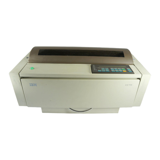
IBM 4247 Dot Matrix Printer Manuals
Manuals and User Guides for IBM 4247 Dot Matrix Printer. We have
1
IBM 4247 Dot Matrix Printer manual available for free PDF download: Maintenance Information
IBM 4247 Maintenance Information (567 pages)
Brand:
IBM
| Category:
Printer
| Size: 6.27 MB
Table of Contents
Maintenance Information
1
Table of Contents
3
Contents
4
Contents
5
Contents
6
Contents
7
Safety Information
9
Safety Notices
9
General Safety
11
Electrical Safety
13
Pre-Service Inspection
15
Model A00 Publications
17
Models 001 and 002 Publications
17
Related Publications
17
Common Publications
18
Model 003 Publications
18
Preface - What's New in the Model 003
19
Chapter 1. Diagnosing Problems
20
Maintenance Analysis Procedures (Maps)
20
Defining the Problem
20
Map 0100: Start of Call
23
MAP 0110: Automatic Sheet Feeder
26
MAP 0120: Parallel or Serial Attachment, Model A00 and Model 003
33
MAP 0121: Parallel with Twinax or Coax Attachments, Models 001, 002, or 003
41
Attachment Card Procedure 1
50
Attachment Card Procedure 2
56
MAP 0122: Network Print Server Attachment
59
MAP 0130: no Paper Movement
62
MAP 0131: Paper Path Sensor
66
MAP 0140: Printhead Drive
70
MAP 0150: Power Supply
75
MAP 0160: Ribbon Feed and Ribbon Lift
89
MAP 0170: ASF Stacker
94
MAP 0180: Top Cover Interlock
98
MAP 0190: Form Feed Problems
101
MAP 0200: 55 AFTA Errors
127
MAP 0210: Intermittent Failures
130
Maps Reference Tables
133
Reference Table 1, Model A00 Error Messages
133
Reference Table 2, Models 001, 002, and 003 Error Messages
136
Reference Table 3, no Printed Characters
146
Reference Table 4, Print Quality Failures
146
Reference Table 5, Operator Panel and Miscellaneous Problems
149
Reference Table 6, LED and Test Page Problems - NPS and LAN Attachment Card
152
Reference Table 7, Network Server Problems - NPS and LAN Attachment Card
156
Reference Table 8, Power Supply Connector Pins and Voltages
156
Reference Table 9, Base Code Compatibilities
157
Reference Table 10, Ribbon Lift and 26-Pin Cable Connectors
158
Reference Table 11, Paper Paths
158
Reference Table 12, Minimum Microcode
158
Chapter 2. Diagnostics
160
Test and Diagnostic Information - Model A00
160
How to Print the Print Test
160
How to Print Firmware Part Number and Version Levels
160
How to Print the Power on Configuration
160
How to Print the Program Setup Configuration
161
How to Run the Test and Diagnostic (T&D) Programs
161
T&D Descriptions
164
T&D Error Messages and Actions
190
Test and Diagnostic Information - Models 001, 002, and 003
197
How to Print the Printer Demonstration
197
How to Print Firmware Part Number and Version Levels
197
How to Print the Printer Configuration and the Custom Sets
198
How to Print and Clear the Error Log, and Print the Usage Metrics
198
How to Run the Test and Diagnostic (T&D) Programs
201
T&D Descriptions
204
T&D Error Messages and Actions - Models 001, 002, and 003
231
Chapter 3. Circuit Diagrams
240
Wiring Diagrams
240
Printhead and Motors Wiring Diagrams
240
Carriage Motor Wiring
246
Cable Diagrams
258
Attachment Connectors
262
Chapter 4. Locations
265
Locations and Orientations
266
Logic Board Microcode Module Locations and Orientation - Model A00
266
Logic Board Microcode Module Locations and Orientation - Models 001 and 002
268
Attachment Card Microcode Module Location and Orientation - Models 001 and 002
269
Microcode Module Label - Model A00
270
Microcode Module Label - Models 001 and 002
270
Connector Locations - Early Model A00
271
Connector Locations - Later Model A00, and Models 001 and 002
272
Connector Locations - Model 003
273
Network Print Server Attachment Pin 18 +5 V Jumper Location and the Parallel Connector
273
Chapter 5. Removals and Adjustments
275
Service Position
275
Service Checks and Adjustments
279
Carriage Drive Belt
279
Carriage Support Shaft
280
Paper Feed Belt
281
Automatic Forms Thickness Adjustment (AFTA)
282
Standard Afta Service Check and Adjustment
285
First Line Printing
294
Bidirectional Printing
294
Tear-Off Line
295
Sensor Service Checks
296
Paper Path Service Checks
301
Automatic Sheet Feeder (ASF) Bins Service Check
319
ASF Stacker Service Check
322
Platen Pinch Roller Assembly Service Check
323
Tractor Assembly Service Check
325
Ribbon Feed and Ribbon Lift Service Check
330
Printhead Drive Service Check
333
Print Quality Checks
338
Removals/Replacements
346
Overview
346
Printer Covers
347
Ribbon
353
Operator Panel
355
Printhead
356
Model 003 Attachment Cards: Serial, Twinax, LAN, Coax
359
Attachment Card Guide Assembly with the Interposer Connector (Model 003)
364
Logic Board - Model 003
366
Logic Board - Model A00
370
EMI Filter (Model A00 Early-Level Logic Board Only)
377
Logic Board - Models 001 and 002
378
Logic Board Component Inspection Reference
385
Serial Attachment Card - Model A00
390
Coax Attachment Card - Models 001, and 002
392
Twinax Attachment Card - Models 001, and 002
396
Power Supply
400
Ribbon Drive Motor
403
Ribbon Lift Motor
405
Automatic Forms Thickness Adjust (AFTA) Assembly
407
Platen Pinch Roller Assembly
411
Carriage Drive Motor Assembly
415
Carriage Drive Belt
420
Paper Bail Assembly
422
Manual Sheet Feed Tray
425
Upper Feed Roller Shaft Assembly
426
Platen Assembly
429
Printhead Mask
432
Lower Feed Roller Assembly
435
Carriage Assembly
437
Carriage Support Shaft
439
Sensor Cable Assembly
441
Printer Mechanical Assembly
444
Paper Feed Motor
447
Paper Feed Motor Drive Belt
448
Lower Plastic Shield/Support Assembly
451
Chapter 6. Parts Catalog
457
How to Use this Parts Catalog
457
Assemblies
459
Assembly 1: Covers and Operator Panel
460
Assembly 2: Tractor Assembly, Automatic Sheet Feeder, and Stacker
463
Assembly 3: Printer Mechanical Assembly and Base
465
Assembly 4: Mechanical Assembly I
467
Assembly 5: Mechanical Assembly II
470
Assembly 6: Mechanical Assembly III
473
Assembly 7: Electronics I
475
Assembly 8: Electronics II
477
Assembly 9: Printhead and Cables
479
Assembly 10: Power Cords, Parts Kits, and Tools
481
Chapter 7. Preventative Maintenance
483
Appendix A. Printer Configuration
484
Configuration Information - All Models
484
Overview
484
Model A00 Configuration Information
485
Models 001, 002, and 003 Configuration Information
499
Appendix B. Supplies, Forms, Paths, & Environmental Considerations
531
Overview
531
Supplies
531
Choosing a Forms Path for Your Needs
531
Choosing a Forms Path for Special Forms
532
Other Considerations for Forms
533
Forms and Paper Specifications
534
Forms Stacking Recommendations
539
Forms Stack Input and Output Locations
540
Forms Paths
541
Rear Push Forms Path
542
Dual Push Forms Path
543
Automatic Sheet Feeder Paper Path
545
Environmental Requirements
546
Operating Environment
546
Nonoperating Environment
547
Shipping Environment
547
Storage Environment
548
Appendix C. Flashing the Memory of the Model 003
549
Flashing the Memory of the Model 003
549
Downloading Model 003 Microcode from the IBM First Service System II Data Base
549
Downloading Model 003 Microcode from Your Computer into the Flash Memory
551
Part Number Index
557
Index
561
Advertisement
Advertisement
Related Products
IBM 4247 - Model 001 B/W Dot-matrix Printer
IBM 4247-V03
IBM 4247 A00
IBM 4247 001
IBM 4247 002
IBM 4247 Model 003
IBM 4232 PRINTER MODEL 302
IBM 4230 2I1
IBM 4230 4I3
IBM 4230 101
IBM Categories
Server
Desktop
Storage
Laptop
Monitor
More IBM Manuals
Login
Sign In
OR
Sign in with Facebook
Sign in with Google
Upload manual
Upload from disk
Upload from URL