Sign In
Upload
Manuals
Brands
IBM Manuals
Server
Power System 8247-21L
IBM Power System 8247-21L Power8 Server Manuals
Manuals and User Guides for IBM Power System 8247-21L Power8 Server. We have
6
IBM Power System 8247-21L Power8 Server manuals available for free PDF download: Manual, Installing
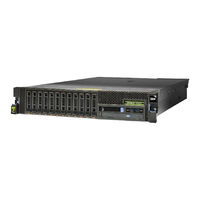
IBM Power System 8247-21L Manual (204 pages)
Disk drives or solid-state drives
Brand:
IBM
| Category:
Server
| Size: 35.93 MB
Table of Contents
Table of Contents
5
Safety Notices
9
Disk Drives or Solid-State Drives for the 5148-21L, 5148-22L, 8247-21L, 8247-22L, 8284-21A, or 8284-22A
19
Installing a Disk Drive or Solid-State Drive in the 5148-21L, 5148-22L, 8247-21L, 8247-22L, 8284-21A, or 8284-22A
19
Installing a Disk Drive or Solid-State Drive in the 5148-21L, 5148-22L, 8247-21L, 8247-22L, 8284-21A, or 8284-22A System with the Power Turned off
19
Power Turned off
19
Preparing the 5148-21L, 5148-22L, 8247-21L, 8247-22L, 8284-21A, or 8284-22A System to Install a Disk Drive with the Power Turned off
20
With the Power Turned off
20
Installing a Disk Drive in the 5148-21L, 5148-22L, 8247-21L, 8247-22L, 8284-21A, or 8284-22A System with the Power Turned off
23
The Power Turned off
23
Installing a Solid-State Drive in the Expanded Function 5148-21L, 5148-22L, 8247-21L, 8247-22L, 8284-21A, or 8284-22A System with the Power Turned off
25
Preparing the 5148-21L, 5148-22L, 8247-21L, 8247-22L, 8284-21A, or 8284-22A System for Operation after Installing a Disk Drive with the Power Turned off
25
Preparing the Expanded Function 5148-21L, 5148-22L, 8247-21L, 8247-22L, 8284-21A, or 8284-22A System to Install a Solid-State Drive with the Power Turned off
26
Or 8284-22A System with the Power Turned off
28
Preparing the Expanded Function 5148-21L, 5148-22L, 8247-21L, 8247-22L, 8284-21A, or 8284-22A System for Operation after Installing a Solid-State Drive with the Power Turned off
30
Aix
31
Preparing the 8284-21A or 8284-22A System to Install a Disk Drive or Solid-State Drive with the Power Turned on in AIX
32
Aix
34
Preparing the 8284-21A or 8284-22A System for Operation after Installing a Disk Drive or Solid-State Drive with the Power Turned on in AIX
38
Installing a Disk Drive or Solid-State Drive in the 8284-21A or 8284-22A System with the Power Turned on in IBM I
39
Preparing the 8284-21A or 8284-22A System to Install a Disk Drive or Solid-State Drive with the Power Turned on in IBM I
40
Installing a Disk Drive or Solid-State Drive in the 8284-21A or 8284-22A System with the Power Turned on in IBM I
42
Preparing the 8284-21A or 8284-22A System for Operation after Installing a Drive with the Power Turned on in IBM I
46
Installing a Disk Drive or Solid-State Drive in the 5148-21L, 5148-22L, 8247-21L, 8247-22L, 8284-21A, or 8284-22A System with the Power Turned on in Linux
47
Or Solid-State Drive with the Power Turned on in Linux
48
Installing a Disk Drive or Solid-State Drive in the 5148-21L, 5148-22L, 8247-21L, 8247-22L, 8284-21A, or 8284-22A System with the Power Turned on in Linux
50
Installing a Disk Drive or Solid-State Drive with the Power Turned on in Linux
54
Removing and Replacing a Disk Drive or Solid-State Drive in the 5148-21L, 5148-22L, 8247-21L, 8247-22L, 8284-21A, or 8284-22A
56
Removing and Replacing a Disk Drive or Solid-State Drive in the 5148-21L, 5148-22L, 8247-21L, 8247-22L, 8284-21A, or 8284-22A with the System Power Turned off
56
A Disk Drive or Solid-State Drive with the Power Turned off
57
Removing a Disk Drive or Solid-State Drive from the 5148-21L, 5148-22L, 8247-21L, 8247-22L, 8284-21A, or 8284-22A System with the Power Turned off
60
Replacing a Disk Drive or Solid-State Drive in the 5148-21L, 5148-22L, 8247-21L, 8247-22L, 8284-21A, or 8284-22A System with the Power Turned off
63
Preparing the 5148-21L, 5148-22L, 8247-21L, 8247-22L, 8284-21A, or 8284-22A System for Operation after Removing and Replacing a Drive with the Power Turned off
65
Removing and Replacing a Disk Drive or Solid-State Drive in the 8284-21A or 8284-22A System with the Power Turned on in AIX
67
Preparing the 8284-21A or 8284-22A System to Remove and Replace a Disk Drive or Solid-State Drive with the Power Turned on in AIX
67
Removing a Disk Drive or Solid-State Drive from the 8284-21A or 8284-22A System with the Power Turned on in AIX
69
Aix
72
Preparing the 8284-21A or 8284-22A System for Operation after Replacing a Drive with the Power Turned on in AIX
75
Removing and Replacing a Disk Drive or Solid-State Drive in the 8284-21A or 8284-22A System with the Power Turned on in IBM I
76
Preparing the 8284-21A or 8284-22A System to Remove and Replace a Disk Drive or Solid-State Drive with the Power Turned on in IBM I
77
Removing a Disk Drive or Solid-State Drive from the 8284-21A or 8284-22A System with the Power Turned on in IBM I
81
Replacing a Disk Drive or Solid-State Drive in the 8284-21A or 8284-22A System with the Power Turned on in IBM I
84
Preparing the 8284-21A or 8284-22A System for Operation after Removing and Replacing a Drive with the Power Turned on in IBM I
88
Removing and Replacing a Disk Drive or Solid-State Drive by Using the Hot-Spare Function in the 8284-21A or 8284-22A System with the Power Turned on in IBM I
89
The Hot-Spare Function with the Power Turned on in IBM I
90
Removing a Hot-Spare Disk Drive or Solid-State Drive from the 8284-21A or 8284-22A System with the Power Turned on in IBM I
93
Replacing a Hot-Spare Disk Drive or Solid-State Drive in the 8284-21A or 8284-22A System with the Power Turned on in IBM I
96
Preparing the 8284-21A or 8284-22A System for Operation after Removing and Replacing a Hot-Spare Drive with the Power Turned on in IBM I
100
8284-21A, or 8284-22A with the Power Turned on in Linux
102
A Disk Drive or Solid-State Drive with the Power Turned on in Linux
102
Removing and Replacing a Disk Drive or Solid-State Drive in the 5148-21L, 5148-22L, 8247-21L, 8247-22L 8284-21A, or 8284-22A with the Power Turned on in Linux
102
Removing a Disk Drive or Solid-State Drive from the 5148-21L, 5148-22L, 8247-21L, 8247-22L, 8284-21A, or 8284-22A System with the Power Turned on in Linux
106
Replacing a Disk Drive or Solid-State Drive in the 5148-21L, 5148-22L, 8247-21L, 8247-22L, 8284-21A, or 8284-22A System with the Power Turned on in Linux
109
Preparing the 5148-21L, 5148-22L, 8247-21L, 8247-22L, 8284-21A, or 8284-22A System for Operation after Removing and Replacing a Drive with the Power Turned on in Linux
113
Related Procedures for Installing, Removing, and Replacing Disk Drives or Solid-State Drives
115
Internal Disk Drive Sharing on an 5148-21L, 5148-22L, 8247-21L, 8247-22L, 8284-21A, or 8284-22A System
115
Removing and Installing a Disk Drive Filler
115
Removing a Disk Drive Filler from the 5148-21L, 5148-22L, 8247-21L, 8247-22L, 8284-21A, or 8284-22A
115
Installing a Disk Drive Filler in the 5148-21L, 5148-22L, 8247-21L, 8247-22L, 8284-21A, or 8284-22A
117
Disk Drive or Solid-State Drive Locations and Service Indicators
119
Disk Drive Locations and Service Indicators for the 5148-21L, 5148-22L, 8247-21L, 8247-22L, 8284-21A, or 8284-22A System
119
Disk Drive Locations and Service Indicators for the 5887 Disk Drive Enclosure
119
Disk Drive Locations and Service Indicators for the ESLL and ESLS Storage Enclosures
121
Solid-State Drive Configuration Rules
122
Mainstream Solid-State Drives
126
Using the AIX Fuel Gauge Command
128
Using the IBM I Fuel Gauge Tool
129
Using the Linux Fuel Gauge Command
130
Preparing the System to Remove a Disk Drive or Solid-State Drive
131
Preparing the System to Remove a Disk Drive or Solid-State Drive from a System or Logical Partition Controlled by IBM I
131
Preparing the System to Remove a Disk Drive or Solid-State Drive in AIX
131
Preparing the System to Remove a Disk Drive or Solid-State Drive in Linux
132
Configuring a Disk Drive or Solid-State Drive
132
Configuring a Disk Drive or Solid-State Drive for Use in an AIX System or AIX Logical Partition
132
Configuring a Disk Drive or Solid-State Drive for Use in an IBM I System or IBM I Logical Partition
133
Configuring a Disk Drive or Solid-State Drive on a Load Source Adapter for Hot-Spare Protection by Using the IBM I Operating System
135
Configuring a Disk Drive or Solid-State Drive for Use in an Linux System or Linux Logical Partition
136
Determining the Disk Drive or Solid-State Drive Protection Status in the IBM I Operating System
136
Rebuilding Data on a Replacement Disk Drive or Solid-State Drive
137
Rebuilding Data on a Replacement Disk Drive or Solid-State Drive in a System or Logical Partition Running the AIX Operating System
137
Rebuilding Data on a Replacement Disk Drive or Solid-State Drive in a System or Logical Partition Running the IBM I Operating System
138
Rebuilding Data by Using the Iprconfig Command
139
Rebuilding Data on a Replacement Disk Drive or Solid-State Drive in a System or Logical Partition that Is Running the Linux Operating System
139
Common Procedures for Installing, Removing and Replacing Disk Drives or Solid-State Drives
141
Before You Begin
141
Identifying a Part
144
Identifying the Enclosure or Server that Contains the Part
144
Control Panel Leds
144
Enabling Enclosure or Server Indicators with the ASMI
144
Activating an Identify LED for an Enclosure or Server by Using the HMC
145
Finding the Part Location Code and LED Support Status
146
Identifying a Part by Using the Operating System or VIOS
147
Finding the Location Code for a Part in an AIX System or Logical Partition
147
Identifying a Part in an AIX System or Logical Partition
147
Activating the Indicator Light for a Part by Using AIX Diagnostics
148
Finding the Location Code and Activating the Indicator Light for a Part by Using the IBM I Operating System
148
Identifying a Part in an IBM I System or Logical Partition
148
Activating the Indicator Light for a Part by Using the Linux Operating System
149
Finding the Location Code of a Part in a Linux System or Logical Partition
149
Finding the Location Code of a Part in a VIOS System or Logical Partition
149
Identifying a Part in a Linux System or Logical Partition
149
Identifying a Part in a VIOS System or Logical Partition
149
Activating the Indicator Light for a Part by Using the VIOS Tools
150
Identifying a Part by Using the ASMI
150
Activating the Identify LED by Using the ASMI When You Know the Location Code
150
Activating the Identify LED by Using the ASMI When You Do Not Know the Location Code
151
Identifying a Part by Using the HMC
151
Stopping a System or Logical Partition
152
Stopping a System that Is Not Managed by an HMC
152
Stopping a System by Using the Control Panel
152
Stopping a System by Using the ASMI
153
Stopping a System by Using the HMC
153
Stopping a System by Using the HMC Classic or HMC Enhanced Interface
153
Stopping a System by Using the HMC Enhanced + Tech Preview (Pre-GA) or HMC Enhanced+ Interface
154
Stopping an IBM Powerkvm System
154
Starting the System or Logical Partition
154
Starting a System that Is Not Managed by an HMC
155
Starting a System by Using the Control Panel
155
Starting a System by Using the ASMI
156
Starting a System or Logical Partition by Using the HMC
156
Starting a System or Logical Partition by Using the HMC Classic or HMC Enhanced Interface
156
Starting a System or Logical Partition by Using the HMC Enhanced + Tech Preview (Pre-GA) or HMC Enhanced+ Interface
157
Starting an IBM Powerkvm System
157
Installing or Replacing a Part with an HMC
158
Installing a Part by Using the HMC
158
Removing a Part by Using the HMC
159
Repairing a Part by Using the HMC
159
Power Cords
160
Disconnecting the Power Cords from the System
160
Connecting the Power Cords to the System
163
Removing and Replacing Covers on the 5148-21L, 5148-22L, 8247-21L, 8247-22L, 8247-42L, 8284-21A, 8284-22A, 8286-41A, or 8286-42A System
166
Removing the Front Cover
166
Removing the Front Cover from a Rack-Mounted 5148-21L, 5148-22L, 8247-21L, 8247-22L, 8284-21A, or 8284-22A System
166
Removing the Front Cover from a Rack-Mounted 8247-42L, 8286-41A, or 8286-42A System
166
Removing the Front Cover from a Stand-Alone 8286-41A System
167
Removing the Side Cover from a Stand-Alone 8286-41A System with an Internal RDX Docking Station
168
Installing the Front Cover
171
Installing the Front Cover on a Rack-Mounted 5148-21L, 5148-22L, 8247-21L, 8247-22L, 8284-21A, or 8284-22A System
171
Installing the Front Cover on a Rack-Mounted 8247-42L, 8286-41A, or 8286-42A System
172
Installing the Front Cover and Front Door on a Stand-Alone 8286-41A System
173
Installing the Side Cover on a Stand-Alone 8286-41A System with an Internal RDX Docking Station
174
Removing the Service Access Cover from a 5148-21L, 5148-22L, 8247-21L, 8247-22L, 8247-42L, 8284-21A, 8284-22A, 8286-41A, or 8286-42A System
177
Removing the Service Access Cover from a Rack-Mounted 5148-21L, 5148-22L, 8247-21L, 8247-22L, 8247-42L, 8284-21A, 8284-22A, 8286-41A, or 8286-42A System
177
Removing the Service Access Cover from a Stand-Alone 8286-41A System
178
Installing the Service Access Cover on a 5148-21L, 5148-22L, 8247-21L, 8247-22L, 8247-42L, 8284-21A, 8284-22A, 8286-41A, or 8286-42A System
179
Installing the Service Access Cover on a Rack-Mounted 5148-21L, 5148-22L, 8247-21L, 8247-22L, 8247-42L, 8284-21A, 8284-22A, 8286-41A, or 8286-42A System
179
Installing the Service Access Cover on a Stand-Alone 8286-41A System
180
Air Baffle
181
Opening the Air Baffle on an 8247-42L, 8286-41A, or 8286-42A System
181
Closing the Air Baffle on an 8247-42L, 8286-41A, or 8286-42A System
182
Removing the Air Baffle from an 8247-42L, 8286-41A, or 8286-42A System
183
Replacing the Air Baffle on an 8247-42L, 8286-41A, or 8286-42A System
184
Deactivating an Identify LED
185
Deactivating a System Attention LED by Using the Operating System or VIOS Tools
185
Deactivating the Indicator Light for a Part by Using AIX Diagnostics
185
Deactivating the Indicator Light by Using the IBM I Operating System
186
Deactivating the Indicator Light by Using the Linux Operating System
186
Deactivating the Indicator Light for a Part by Using the VIOS Tools
186
Deactivating a System Attention LED by Using the ASMI
187
Deactivating the Identify LED by Using the ASMI When You Do Not Know the Location Code
187
Deactivating the Identify LED by Using the ASMI When You Know the Location Code
187
Deactivating a Check Log Indicator (System Information Indicator) by Using the ASMI
188
Deactivating Leds by Using the HMC
188
Deactivating a System Attention LED or Partition LED by Using the HMC
188
Deactivating an Identify LED for a FRU by Using the HMC
189
Deactivating an Identify LED for an Enclosure by Using the HMC
189
Notices
191
Accessibility Features for IBM Power Systems Servers
192
Privacy Policy Considerations
193
Trademarks
194
Electronic Emission Notices
194
Class a Notices
194
Class B Notices
198
Terms and Conditions
201
Advertisement
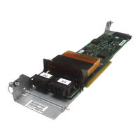
IBM Power System 8247-21L Manual (130 pages)
Brand:
IBM
| Category:
Adapter
| Size: 19.5 MB
Table of Contents
Table of Contents
5
Safety Notices
9
Pcie3 X8 SAS RAID Internal Adapter 6 Gb for the 5148-21L, 5148-22L, 8247-21L, 8247-22L, 8284-21A, or 8284-22A
19
Installing the Pcie3 X8 SAS RAID Internal Adapter 6 Gb in the 5148-21L, 5148-22L, 8247-21L, 8247-22L, 8284-21A, or 8284-22A
19
Preparing the System to Install a Pcie3 X8 SAS RAID Internal Adapter 6 Gb
19
Installing the Pcie3 X8 SAS RAID Internal Adapter 6 Gb in the 5148-21L, 5148-22L, 8247-21L, 8247-22L, 8284-21A, or 8284-22A
20
Preparing the System for Operation after Installing a Pcie3 X8 SAS RAID Internal Adapter 6 Gb
26
Removing and Replacing the Pcie3 X8 SAS RAID Internal Adapter 6 Gb in the 5148-21L, 5148-22L, 8247-21L, 8247-22L, 8284-21A, or 8284-22A
26
Preparing the System to Remove and Replace the Pcie3 X8 SAS RAID Internal Adapter 6 Gb
26
Removing the Pcie3 X8 SAS RAID Internal Adapter 6 Gb from the 5148-21L, 5148-22L, 8247-21L, 8247-22L, 8284-21A, or 8284-22A
30
Replacing the Pcie3 X8 SAS RAID Internal Adapter 6 Gb in the 5148-21L, 5148-22L, 8247-21L, 8247-22L, 8284-21A, or 8284-22A
32
Preparing the System for Operation after Removing and Replacing the Pcie3 X8 SAS RAID Internal Adapter 6 Gb
35
Common Procedures for Removing or Replacing the Pcie3 X8 SAS RAID Internal Adapter 6 Gb
37
Before You Begin
37
Identifying a Part
40
Identifying the Enclosure or Server that Contains the Part
40
Control Panel Leds
40
Enabling Enclosure or Server Indicators with the ASMI
40
Activating an Identify LED for an Enclosure or Server by Using the HMC
41
Finding the Part Location Code and LED Support Status
42
Identifying a Part by Using the Operating System or VIOS
43
Activating the Indicator Light for a Part by Using AIX Diagnostics
43
Finding the Location Code for a Part in an AIX System or Logical Partition
43
Identifying a Part in an AIX System or Logical Partition
43
Finding the Location Code and Activating the Indicator Light for a Part by Using the IBM I Operating System
44
Identifying a Part in an IBM I System or Logical Partition
44
Activating the Indicator Light for a Part by Using the Linux Operating System
45
Finding the Location Code of a Part in a Linux System or Logical Partition
45
Finding the Location Code of a Part in a VIOS System or Logical Partition
45
Identifying a Part in a Linux System or Logical Partition
45
Identifying a Part in a VIOS System or Logical Partition
45
Activating the Indicator Light for a Part by Using the VIOS Tools
46
Identifying a Part by Using the ASMI
46
Activating the Identify LED by Using the ASMI When You Know the Location Code
46
Activating the Identify LED by Using the ASMI When You Do Not Know the Location Code
47
Identifying a Part by Using the HMC
47
Starting the System or Logical Partition
48
Starting a System that Is Not Managed by an HMC
48
Starting a System by Using the Control Panel
48
Starting a System by Using the ASMI
50
Starting a System or Logical Partition by Using the HMC
50
Starting a System or Logical Partition by Using the HMC Classic or HMC Enhanced Interface
50
Starting a System or Logical Partition by Using the HMC Enhanced + Tech Preview (Pre-GA) or HMC Enhanced+ Interface
50
Starting an IBM Powerkvm System
51
Stopping a System or Logical Partition
51
Stopping a System that Is Not Managed by an HMC
51
Stopping a System by Using the ASMI
52
Stopping a System by Using the Control Panel
52
Stopping a System by Using the HMC
52
Stopping a System by Using the HMC Classic or HMC Enhanced Interface
53
Stopping a System by Using the HMC Enhanced + Tech Preview (Pre-GA) or HMC Enhanced+ Interface
53
Stopping an IBM Powerkvm System
53
Removing and Replacing Covers on the 5148-21L, 5148-22L, 8247-21L, 8247-22L, 8247-42L, 8284-21A, 8284-22A, 8286-41A, or 8286-42A System
54
Removing the Front Cover
54
Removing the Front Cover from a Rack-Mounted 5148-21L, 5148-22L, 8247-21L, 8247-22L, 8284-21A, or 8284-22A System
54
Removing the Front Cover from a Rack-Mounted 8247-42L, 8286-41A, or 8286-42A System
55
Removing the Front Cover from a Stand-Alone 8286-41A System
56
Removing the Side Cover from a Stand-Alone 8286-41A System with an Internal RDX Docking Station
57
Installing the Front Cover
60
Installing the Front Cover on a Rack-Mounted 5148-21L, 5148-22L, 8247-21L, 8247-22L, 8284-21A, or 8284-22A System
60
Installing the Front Cover on a Rack-Mounted 8247-42L, 8286-41A, or 8286-42A System
61
Installing the Front Cover and Front Door on a Stand-Alone 8286-41A System
62
Installing the Side Cover on a Stand-Alone 8286-41A System with an Internal RDX Docking Station
63
Removing the Service Access Cover from a 5148-21L, 5148-22L, 8247-21L, 8247-22L, 8247-42L, 8284-21A, 8284-22A, 8286-41A, or 8286-42A System
66
Removing the Service Access Cover from a Rack-Mounted 5148-21L, 5148-22L, 8247-21L, 8247-22L, 8247-42L, 8284-21A, 8284-22A, 8286-41A, or 8286-42A System
66
Removing the Service Access Cover from a Stand-Alone 8286-41A System
67
Installing the Service Access Cover on a 5148-21L, 5148-22L, 8247-21L, 8247-22L, 8247-42L, 8284-21A, 8284-22A, 8286-41A, or 8286-42A System
68
Installing the Service Access Cover on a Rack-Mounted 5148-21L, 5148-22L, 8247-21L, 8247-22L, 8247-42L, 8284-21A, 8284-22A, 8286-41A, or 8286-42A System
68
Installing the Service Access Cover on a Stand-Alone 8286-41A System
69
Air Baffle
70
Opening the Air Baffle on an 8247-42L, 8286-41A, or 8286-42A System
70
Closing the Air Baffle on an 8247-42L, 8286-41A, or 8286-42A System
71
Removing the Air Baffle from an 8247-42L, 8286-41A, or 8286-42A System
72
Replacing the Air Baffle on an 8247-42L, 8286-41A, or 8286-42A System
73
Service and Operating Positions for the 5148-21L, 5148-22L, 8247-21L, 8247-22L, 8247-42L, 8284-21A, 8284-22A, 8286-41A, or 8286-42A System
74
Placing the Rack-Mounted System into the Service Position
74
Placing the Rack-Mounted System into the Operating Position
76
Power Cords
76
Disconnecting the Power Cords from the System
76
Connecting the Power Cords to the System
79
Installing or Replacing a Part with an HMC
82
Installing a Part by Using the HMC
82
Removing a Part by Using the HMC
82
Repairing a Part by Using the HMC
83
Verifying the Installed Part
84
Verifying a Part by Using the Operating System or VIOS
84
Verifying an Installed Feature by Using the AIX Operating System
84
Verifying an Installed Feature or Replaced Part by Using an AIX System or Logical Partition
84
Verifying a Replaced Part by Using the AIX Operating System
85
Verifying an Installed Part by Using a Linux System or Logical Partition
87
Verifying an Installed Part by Using Stand-Alone Diagnostics
87
Verifying the Installed Part by Using an IBM I System or Logical Partition
87
Verify the Replacement Part by Using VIOS
89
Verifying an Installed Part by Using VIOS
89
Verifying an Installed Part or Replaced Part on a System or Logical Partition by Using Virtual I/O Server Tools
89
Verifying the Installed Part by Using the HMC
91
Viewing Serviceable Events by Using the HMC
92
Verifying a Repair
92
Verifying the Repair in AIX
93
Verifying a Repair by Using an IBM I System or Logical Partition
96
Verifying the Repair in Linux
98
Verifying the Repair on an IBM Powerkvm System
98
Verifying the Repair from the Management Console
99
Closing a Service Call
100
Closing a Service Call by Using AIX or Linux
103
Closing a Service Call by Using IBM Powerkvm
106
Closing a Service Call by Using Integrated Virtualization Manager
107
Activating and Deactivating Leds
109
Deactivating a System Attention LED or Partition LED by Using the Management Console
110
Activating or Deactivating an Identify LED by Using the Management Console
111
Deactivating a System Attention LED or Logical Partition LED by Using the Advanced System Management Interface
112
Activating or Deactivating an Identify LED by Using the Advanced System Management Interface
112
Deactivating an Identify LED
113
Deactivating a System Attention LED by Using the Operating System or VIOS Tools
113
Deactivating the Indicator Light for a Part by Using AIX Diagnostics
113
Deactivating the Indicator Light by Using the IBM I Operating System
113
Deactivating the Indicator Light by Using the Linux Operating System
114
Deactivating the Indicator Light for a Part by Using the VIOS Tools
114
Deactivating a System Attention LED by Using the ASMI
114
Deactivating a Check Log Indicator (System Information Indicator) by Using the ASMI
115
Deactivating the Identify LED by Using the ASMI When You Do Not Know the Location Code
115
Deactivating the Identify LED by Using the ASMI When You Know the Location Code
115
Deactivating Leds by Using the HMC
116
Deactivating a System Attention LED or Partition LED by Using the HMC
116
Deactivating an Identify LED for a FRU by Using the HMC
117
Deactivating an Identify LED for an Enclosure by Using the HMC
117
Notices
119
Privacy Policy Considerations
120
Trademarks
121
Electronic Emission Notices
121
Class a Notices
121
Class B Notices
125
Terms and Conditions
128
IBM Power System 8247-21L Installing (74 pages)
Brand:
IBM
| Category:
Server
| Size: 6.17 MB
Table of Contents
Table of Contents
5
Safety Notices
7
Determining Your Server Type
17
Installing a Rack-Based Server
17
Prerequisite for Installing the Rack-Mounted Server
17
Completing Inventory for Your Server
18
Determining and Marking the Location in the Rack
18
Attaching the Mounting Hardware to the Rack
20
Installing the 8247-21L System into the Rack
22
Installing the Cable-Management Arm
23
Cabling the Server and Setting up a Console
27
Cabling the Server with an ASCII Terminal
28
Determining Which Console to Use
28
Cabling the Server to the HMC
29
Cabling the Server and Accessing the IVM
31
Cabling the Server and Connecting Expansion Units
32
Cabling the Server with Keyboard, Video, and Mouse
32
Completing the Server Setup
32
Completing the Server Setup Without Using an HMC
33
Installing a Rack-Based Water-Cooled Server
34
Completing Inventory for Your Server
34
Prerequisites for Installing the Water-Cooled System
34
Determining and Marking the Location in the Rack
35
Attaching the Mounting Hardware to the Rack
37
Installing the Cable-Management Arm
39
Installing the Water-Cooled 8247-21L System into the Rack
43
Installing Quick Connects to the Supply and Return Hoses
45
Cabling the Server and Setting up a Console
46
Determining Which Console to Use
46
Routing the Hoses from the System to the Manifold
46
Turning on the Water Source and Bleeding Air from the System
46
Cabling the Server with an ASCII Terminal
47
Cabling the Server to the HMC
48
Cabling the Server and Accessing the IVM
49
Cabling the Server with Keyboard, Video, and Mouse
50
Cabling the Server and Connecting Expansion Units
51
Completing the Server Setup
51
Completing the Server Setup Without Using an HMC
51
Setting up a Preinstalled Server
52
Prerequisite for Installing the Preinstalled Server
52
Completing Inventory for Your Preinstalled Server
53
Removing the Shipping Bracket and Connecting Power Cords and Power Distribution Unit (PDU) for Your Preinstalled Server
53
Cabling the Server and Setting up a Console
55
Determining Which Console to Use
55
Cabling the Server with an ASCII Terminal
56
Cabling the Server to the HMC
57
Cabling the Server and Accessing the IVM
58
Cabling the Server with Keyboard, Video, and Mouse
59
Completing the Server Setup
59
Routing Cables through the Cable-Management Arm and Connecting Expansion Units
59
Completing the Server Setup Without Using an HMC
60
Notices
61
Accessibility Features for IBM Power Systems Servers
62
Privacy Policy Considerations
63
Trademarks
64
Electronic Emission Notices
64
Class a Notices
64
Class B Notices
68
Terms and Conditions
71
Advertisement
IBM Power System 8247-21L Manual (60 pages)
PCIe adapter
Brand:
IBM
| Category:
Adapter
| Size: 2.55 MB
Table of Contents
Table of Contents
5
Safety Notices
7
Pcie Adapter Placement for the 5148-21L, 5148-22L, 8247-21L, 8247-22L, 8284-21A, or 8284-22A
17
Pcie Adapter Placement Rules and Slot Priorities for the 5148-21L, 5148-22L, 8247-21L, 8247-22L, 8284-21A, or 8284-22A
17
Pcie Adapter Placement Rules and Slot Priorities for the EMX0 Pcie Gen3 I/O Expansion Drawer
37
Related Procedures for PCI Adapter Placement
45
Finding the Current System Configuration in IBM I
45
Notices
47
Accessibility Features for IBM Power Systems Servers
48
Privacy Policy Considerations
49
Trademarks
50
Electronic Emission Notices
50
Class a Notices
50
Class B Notices
54
Terms and Conditions
57
IBM Power System 8247-21L Manual (42 pages)
SAS subsystem
Brand:
IBM
| Category:
Server
| Size: 9.34 MB
Table of Contents
Table of Contents
5
Safety Notices
7
SAS Subsystem for the 5148-21L, 5148-22L, 8247-21L, 8247-22L, 8247-42L, 8284-21A, 8284-22A, 8286-41A, or 8286-42A
17
What's New in SAS Subsystem for the 5148-21L, 5148-22L, 8247-21L, 8247-22L, 8247-42L, 8284-21A, 8284-22A, 8286-41A, or 8286-42A
17
SAS Architecture
17
SAS Subsystem Overview
18
SAS Subsystem Storage Configurations
21
SAS Subsystem Base Function Storage Configuration for the 5148-21L, 8247-21L, 8247-22L, 8247-42L, 8284-21A, 8284-22A, 8286-41A, or 8286-42A
22
SAS Subsystem Base Function Storage Configuration with the Split Disk Feature for the 8247-21L, 8247-22L, 8284-22A, 8286-41A, or 8286-42A
24
SAS Subsystem Expanded Function Configuration for the 5148-22L, 8247-21L, 8247-22L, 8284-22A, 8286-41A, or 8286-42A
25
SAS Subsystem Service Considerations
27
Problem Determination and Recovery
28
Notices
29
Accessibility Features for IBM Power Systems Servers
30
Privacy Policy Considerations
31
Trademarks
32
Electronic Emission Notices
32
Class a Notices
32
Class B Notices
36
Terms and Conditions
39
IBM Power System 8247-21L Manual (42 pages)
Managing devices
Brand:
IBM
| Category:
Server
| Size: 1.93 MB
Table of Contents
Table of Contents
5
Safety Notices
7
Managing Devices for the 5148-21L, 5148-22L, 8247-21L, 8247-22L, 8247-42L, 8284-21A, 8284-22A, 8286-41A, or 8286-42A System
17
Managing DVD Drives
17
SATA Slimline DVD-RAM Drive (FC 5771)
17
Managing Removable Disk Drives
18
RDX USB External Docks (FC EU04 and EUA4) and RDX Removable Disk Drives (FC 1107, EU01, EU08, EU15, and EU2T)
18
RDX USB Internal Docking Station (FC EUA3) and Removable Disk Drive for the 8286-41A
23
Notices
29
Accessibility Features for IBM Power Systems Servers
30
Privacy Policy Considerations
31
Trademarks
32
Electronic Emission Notices
32
Class a Notices
32
Class B Notices
36
Terms and Conditions
39
Advertisement
Related Products
IBM Power System 8247-22L
IBM 8248-L4T
IBM Power Systems 8247-42L
IBM Power 740 Express 8205-E6B
IBM iSeries 820
IBM Power System 8284-22A
IBM Power 730 Express 8231-E2D
IBM Power 730 Express 8231-E2C
IBM Power Systems 8286-42A
IBM Power 720 Express 8202-E4C
IBM Categories
Server
Desktop
Storage
Laptop
Monitor
More IBM Manuals
Login
Sign In
OR
Sign in with Facebook
Sign in with Google
Upload manual
Upload from disk
Upload from URL