Sign In
Upload
Manuals
Brands
LG Manuals
Air Conditioner
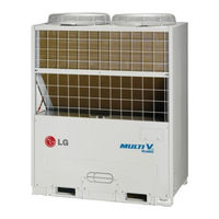
Multi V Plus II ARUN260LT2
LG Multi V Plus II ARUN260LT2 Manuals
Manuals and User Guides for LG Multi V Plus II ARUN260LT2. We have
1
LG Multi V Plus II ARUN260LT2 manual available for free PDF download: Installation Manual
LG Multi V Plus II ARUN260LT2 Installation Manual (97 pages)
Outdoor Unit with R410A Air Conditioner
Brand:
LG
| Category:
Air Conditioner
| Size: 13.25 MB
Table of Contents
Installation Manual
1
Outdoor Unit
1
Table of Contents
2
Safety Precautions
3
Safe Installation
3
Safe Operation
4
Safe Transportation
6
Installation Process
7
Heat Pump Data
8
Power Supply: Outdoor Unit
8
Outdoor Units Information
8
Cooling Only
11
Environment-Friendly Alternative Refrigerant R410A
13
Select the Best Location
13
When Inlet Air Enters from Right and Left Sides of Unit
14
Individual Installation
14
Basic Space Required
14
Installation Space
14
When Unit Is Surrounded by Walls
15
When There Is an Obstruction above the Unit
15
Collective / Continuous Installation
16
Seasonal Wind and Cautions in Winter
17
Lifting Method
18
Location of Anchor Bolt (to be Applied to 1, 2 Units Installation)
19
Installation Foot (Location of Anchor Bolt)
19
Installation
19
Foundation for Installation
20
Foundation Bolt Executing Method
20
Flaring Work
21
Burrs Removal
21
Cut the Pipes and the Cable
21
Preparation of Piping
21
Opening Shutoff Valve
22
Closing Shutoff Valve
22
Flare Shape and Flare Nut Tightening Torque
22
Precautions When Connecting Pipes
22
22 Outdoor Unit
22
Heat Insulation
23
Cautions in Pipe Connection/Valve Operation
24
Refrigerant Piping Installation
24
Connection of High/Low Pressure Common Pipe
25
Outdoor Units
25
Connection of Outdoor Units
26
Materials for Refrigerant Piping
27
Pipe Length between Outdoor Units
28
Refrigerant Piping System
29
Y Branch Method
29
Refrigerant Pipe Diameter from Branch to Branch (B,C,D)
31
Total Pipe Length = A+B+C+D+A+B+C+D+E ≤ 1,000 M
31
Header Method
32
Total Pipe Length = A+A+B+C+D+E+F ≤ 1,000M
33
Combination of y Branch/Header Method
34
Refrigerant Pipe Diameter from Branch to Branch (B,C)
36
Total Pipe Length = A+B+C+A+B+C+D+E ≤ 1,000M
36
Outdoor Unit Connection
37
Indoor Unit Connection
37
Refrigerant Pipe Diameter before 1St Branch (A)
37
Connection between Outdoor and Outdoor Unit
38
Pipe Connection between Outdoors
38
In Case Pipe Length between Outdoors Is Less than 2M
38
In Case Pipe Length between Outdoors Is 2M or more
39
Example of Wrong Connection
39
The Amount of Refrigerant
40
Special Condition
40
Additional Refrigerant Charging Amount (Kg)
40
Indoor Refrigerant Charging Amount
40
Distribution Method
42
Line Distribution
42
Vertical Distribution
42
Branch Pipe Fitting
44
Y Branch Pipe
46
Header
47
Leak Test and Vacuum Drying
48
Vacuum Mode
50
Thermal Insulation of Refrigerant Piping
51
Penetrations
51
Electrical Wiring
52
Precautions When Laying Power Wiring
53
Control Box and Connecting Position of Wiring
54
Communication and Power Lines
55
Communication Cable
55
Simple Central Control Cable
55
Separation of Communication and Power Lines
55
Wiring of Main Power Supply and Equipment Capacity
56
Example Connection of Communication Cable
57
Location of Setting Switch
64
Main Pcb
64
DIP Switch Setting
65
Checking According to Dip Switch Setting
65
Checking the Setting of the Master Unit
65
Model Code
65
Settings of Master Outdoor Unit
66
Setting the DIP Switch
66
Settings of Slave Outdoor Unit
68
Settings of Corresponding Outdoor Unit
68
Automatic Addressing
69
Group Number Setting for Indoor Units
70
Outdoor Unit Dry Contact Installation and Connection
71
Test Run
72
How to Cope with Test Run Abnormality
73
The Phenomena from Main Component Failure
73
Sensor Checking Function
74
Sensor Check Error Code Display
75
Displaying Error Content
75
Refrigerant Auto Charging Function
76
Error Contents about Auto Refrigerant Charging Function
77
Refrigerant Checking Function
78
How to Cope with Result of Refrigerant Checking
79
Night Low Noise Function
80
Max. RPM Setting Method
80
Select Appropriate RPM Referencing Noise Table
80
Static Pressure Compensation Mode
81
Static Pressure Compensation Dip S/W Setting Method
81
Self-Diagnosis Function
82
Error Indicator
82
Error Display
82
Limiting Concentration
93
Calculate Minimum Room Capacity
93
Caution for Refrigerant Leak
93
Calculate Refrigerant Concentration
94
In Case the Concentration Exceeds the Limit
94
Selecting the Location (Outdoor Unit)
95
Installation Guide at the Seaside
95
Advertisement
Advertisement
Related Products
LG MULTI V PLUS ARUN2608T1
LG MULTI V PLUS ARUN2609T1
LG Multi V Plus II ARUN200LT2
LG Multi V Plus II ARUN220LT2
LG Multi V Plus II ARUN240LT2
LG Multi V Plus II ARUN280LT2
LG MULTI V PLUS ARUN2008T1
LG MULTI V PLUS ARUN2208T1
LG MULTI V PLUS ARUN2408T1
LG MULTI V PLUS ARUN2808T1
LG Categories
Cell Phone
Monitor
LED TV
Washer
Air Conditioner
More LG Manuals
Login
Sign In
OR
Sign in with Facebook
Sign in with Google
Upload manual
Upload from disk
Upload from URL