Sign In
Upload
Manuals
Brands
Mitsubishi Electric Manuals
Recording Equipment
M700V Series
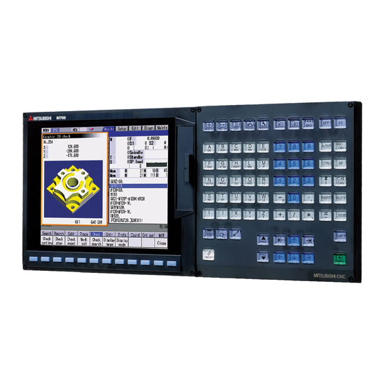
Mitsubishi Electric M700V Series Manuals
Manuals and User Guides for Mitsubishi Electric M700V Series. We have
2
Mitsubishi Electric M700V Series manuals available for free PDF download: Programming Manual, Manual
Mitsubishi Electric M700V Series Programming Manual (609 pages)
Brand:
Mitsubishi Electric
| Category:
Recording Equipment
| Size: 6.31 MB
Table of Contents
Precautions for Safety
7
Table of Contents
9
1 Control Axes
13
Coordinate Words and Control Axis
13
Coordinate Systems and Coordinate Zero Point Symbols
14
2 Least Command Increments
15
Input Setting Units
15
Input Command Increment Tenfold
17
Indexing Increment
18
3 Data Formats
19
Tape Codes
19
Program Formats
22
Tape Memory Format
25
Optional Block Skip
25
Optional Block Skip Addition ; /N
26
Program/Sequence/Block Numbers ; L(O), N
28
Parity H/V
29
G Code Lists
30
Precautions before Starting Machining
33
4 Buffer Register
34
Input Buffer
34
Pre-Read Buffers
35
5 Position Commands
36
Position Command Methods ; G90, G91
36
Inch/Metric Command Change; G20, G21
38
Decimal Point Input
40
6 Interpolation Functions
45
Positioning (Rapid Traverse); G00
45
Linear Interpolation; G01
52
Plane Selection; G17, G18, G19
54
Circular Interpolation; G02, G03
56
R-Specified Circular Interpolation; G02, G03
61
Helical Interpolation ; G17 to G19, G02, G03
64
Thread Cutting
68
Constant Lead Thread Cutting; G33
68
Inch Thread Cutting; G33
72
Unidirectional Positioning; G60
73
Cylindrical Interpolation; G07.1
75
Polar Coordinate Interpolation; G12.1, G13.1
83
Exponential Function Interpolation; G02.3, G03.3
90
Polar Coordinate Command; G16/G15
96
Spiral/Conical Interpolation; G02.0/G03.1(Type1), G02/G03(Type2)
102
3-Dimensional Circular Interpolation; G02.4, G03.4
107
NURBS Interpolation
112
Hypothetical Axis Interpolation; G07
117
7 Feed Functions
119
Rapid Traverse Rate
119
Cutting Feedrate
119
F1-Digit Feed
120
Per-Minute/Per-Revolution Feed (Asynchronous/Synchronous Feed); G94, G95
122
Inverse Time Feed; G93
124
Feedrate Designation and Effects on Control Axes
128
Rapid Traverse Constant Inclination Acceleration/Deceleration
132
Rapid Traverse Constant Inclination Multi-Step Acceleration/Deceleration
134
Exact Stop Check; G09
143
Exact Stop Check Mode; G61
146
Deceleration Check
146
G1 -> G0 Deceleration Check
148
G1 -> G1 Deceleration Check
149
Automatic Corner Override
150
Tapping Mode; G63
155
Cutting Mode; G64
155
8 Dwell
156
Per-Second Dwell ; G04
156
9 Miscellaneous Functions
158
Miscellaneous Functions (M8-Digits BCD)
158
Secondary Miscellaneous Functions (B8-Digits, A8 or C8-Digits)
160
Index Table Indexing
161
10 Spindle Functions
163
Spindle Functions (S6-Digits Analog)
163
Spindle Functions (S8-Digits)
163
Constant Surface Speed Control; G96, G97
164
Constant Surface Speed Control
164
Spindle Clamp Speed Setting; G92
165
Spindle/C Axis Control
166
Multiple Spindle Control
169
Multiple Spindle Control II
170
11 Tool Functions (T Command)
172
Tool Functions (T8-Digit BCD)
172
12 Tool Compensation Functions
173
Tool Compensation
173
Tool Length Compensation/Cancel; G43/G44
177
Tool Length Compensation in the Tool Axis Direction ; G43.1/G44
180
Tool Radius Compensation; G38, G39/G40/G41,G42
187
Tool Radius Compensation Operation
188
Other Commands and Operations During Tool Radius Compensation
197
G41/G42 Commands and I, J, K Designation
206
Interrupts During Tool Radius Compensation
212
General Precautions for Tool Radius Compensation
214
Changing of Compensation No. During Compensation Mode
215
Start of Tool Radius Compensation and Z Axis Cut in Operation
217
Interference Check
219
Diameter Designation of Compensation Amount
226
Workpiece Coordinate Changing During Radius Compensation
228
Three-Dimensional Tool Radius Compensation ; G40/G41,G42
230
Tool Position Offset; G45 to G48
241
Programmed Compensation Input; G10, G11.1
248
Compensation Data Input to Variable by Program; G11
253
Inputting the Tool Life Management Data; G10, G11
254
Inputting the Tool Life Management Data by G10 L3 Command
254
Inputting the Tool Life Management Data by G10 L30 Command
256
Precautions for Inputting the Tool Life Management Data
259
Fixed Cycles
260
Standard Fixed Cycles; G80 to G89, G73, G74, G75, G76
260
13 Program Support Functions
260
Drilling Cycle with High-Speed Retract
288
Initial Point and R Point Level Return; G98, G99
291
Setting of Workpiece Coordinates in Fixed Cycle Mode
293
Special Fixed Cycle; G34, G35, G36, G37
294
Subprogram Control; G22, G22
299
Calling Subprogram with G22 and G22 Commands
299
Figure Rotation; G22 I_ J_ K
303
Variable Commands
306
User Macro Specifications
311
User Macro Commands; G65, G66, G66.1, G67, G68(G23)
311
Macro Call Command
312
ASCII Code Macro
321
Variables
325
Types of Variables
327
Arithmetic Commands
365
Control Commands
370
External Output Commands
373
Precautions
375
Actual Examples of Using User Macros
377
G Command Mirror Image; G50.1, G51.1 / G62
381
Corner Chamfering/Corner Rounding I
384
Corner Chamfering " ,C
384
Corner Rounding " ,R
386
Linear Angle Command
387
Geometric Command
388
Circle Cutting; G12, G13
392
Parameter Input by Program; G10, G11.1
394
Macro Interrupt; ION, IOF
395
Tool Change Position Return; G30.1 to G30.6
403
Normal Line Control ; G40.1/G41.1/G42.1
406
High-Accuracy Control ; G61.1, G08
417
High-Speed Machining Mode; G05, G05.1
431
High-Speed Machining Mode I,II; G05 P1, G05 P2
431
High-Speed High-Accuracy Control; G05, G05.1
434
High-Speed High-Accuracy Control I, II
434
SSS Control
440
Spline; G05.1
445
High-Accuracy Spline Interpolation ; G61.2
452
Scaling; G50/G51
454
Coordinate Rotation by Program; G68.1/G69.1
459
Coordinate Rotation Input by Parameter; G10
467
3-Dimensional Coordinate Conversion; G68.1/69.1
470
Tool Center Point Control; G43.4/G43.5
487
Timing-Synchronization between Part Systems
509
End Point Error Check Cancellation; G69
512
Coordinate Read Function; G14
514
14 Coordinates System Setting Functions
517
Coordinate Words and Control Axes
517
Basic Machine, Workpiece and Local Coordinate Systems
518
Machine Zero Point and 2Nd, 3Rd, 4Th Reference Positions
519
Basic Machine Coordinate System Selection; G53
520
Coordinate System Setting; G92
521
Automatic Coordinate System Setting
522
Reference (Zero) Position Return; G28, G29
523
2Nd, 3Rd and 4Th Reference (Zero) Position Return; G30
527
Reference Position Check; G27
530
Workpiece Coordinate System Setting and Offset ; G54 to G59 (G54.1)
531
Local Coordinate System Setting; G52
543
Workpiece Coordinate System Preset; G92.1
547
Coordinate System for Rotary Axis
552
15 Measurement Support Functions
555
Automatic Tool Length Measurement; G37.1
555
Skip Function; G31
559
Multi-Step Skip Function; G31.N, G04
564
Multi-Step Skip Function 2; G31
566
Speed Change Skip; G31
568
Programmable Current Limitation
571
Stroke Check before Travel; G22.1/G23.1
572
Appendix 1. Program Error
574
Appendix 2. Order of G Function Command Priority
594
Index
603
Revision History
605
Advertisement
Mitsubishi Electric M700V Series Manual (431 pages)
Brand:
Mitsubishi Electric
| Category:
Control Systems
| Size: 19.29 MB
Table of Contents
Table of Contents
4
M System L System
4
M720Vw
5
M System
5
L System
5
M System L System
5
M720Vw
6
M System
6
L System
6
M730Vw M750Vw M720Vs 16 16
7
M730Vw M750Vw M720Vs 4 4
7
M730Vw M750Vw M720Vs 6 6
7
M730Vs M750Vs 16
7
M730Vs M750Vs 4
7
M730Vs M750Vs 6
7
Advertisement
Related Products
Mitsubishi Electric Mac E Series
Mitsubishi Electric MAC-399IF-E
Mitsubishi Electric MAC-568IF-E
Mitsubishi Electric MAC-334IF-E
Mitsubishi Electric MAC-567IFB-E
Mitsubishi Electric MSZ-AP Series
Mitsubishi Electric MSZ-EF Series
Mitsubishi Electric MAC-566IFB-E
Mitsubishi Electric MAC-577IF2-E
Mitsubishi Electric MAC-577IF-E
Mitsubishi Electric Categories
Air Conditioner
Controller
Projector
Inverter
Heat Pump
More Mitsubishi Electric Manuals
Login
Sign In
OR
Sign in with Facebook
Sign in with Google
Upload manual
Upload from disk
Upload from URL