Sign In
Upload
Manuals
Brands
Mitsubishi Electric Manuals
Control Unit
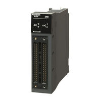
MELSEC iQ-R-RD75D2
Mitsubishi Electric MELSEC iQ-R-RD75D2 Manuals
Manuals and User Guides for Mitsubishi Electric MELSEC iQ-R-RD75D2. We have
1
Mitsubishi Electric MELSEC iQ-R-RD75D2 manual available for free PDF download: User Manual
Mitsubishi Electric MELSEC iQ-R-RD75D2 User Manual (598 pages)
MELSEC iQ-R series Positioning Module (Application)
Brand:
Mitsubishi Electric
| Category:
Control Unit
| Size: 10.87 MB
Table of Contents
Safety Precautions
3
Wiring Precautions
6
Conditions of Use for the Product
11
Introduction
11
Table of Contents
14
Relevant Manuals
20
Terms
20
Chapter 1 Starting and Stopping
21
Starting
21
Normal Start
24
Quick Start
26
Multiple Axes Simultaneous Start
31
Stopping
34
Deceleration Stop
35
Restarting
38
Chapter 2 Opr Control
40
Overview of the OPR Control
40
Two Types of OPR Controls
40
Machine OPR
42
Operation Overview of the Machine OPR
42
Machine OPR Method
43
Near-Point Dog Method
44
Stopper Method 1
46
Stopper Method 2
49
Stopper Method 3
52
Count Method 1
54
Count Method 2
56
Data Setting Method
58
Fast OPR
59
Operation Overview of the Fast OPR
59
Chapter 3 Major Positioning Control
61
Overview of the Major Positioning Controls
61
Data Required for Major Positioning Control
63
Operation Pattern of Major Positioning Control
64
Specifying the Positioning Address
73
Checking the Current Value
74
Handling Degree (Control Unit)
76
Interpolation Control
79
Positioning Data Setting
84
Relation between each Control and Positioning Data
84
1-Axis Linear Control
86
2-Axis Linear Interpolation Control
88
3-Axis Linear Interpolation Control
92
4-Axis Linear Interpolation Control
96
Fixed-Feed Control
98
2-Axis Circular Interpolation Control with the Sub Point Specified
101
2-Axis Circular Interpolation Control with the Center Point Specified
105
3-Axis Helical Interpolation Control with Sub Point Specified
111
3-Axis Helical Interpolation Control with Center Point Specified
117
Speed Control
124
Speed-Position Switching Control (INC Mode)
127
Speed-Position Switching Control (ABS Mode)
134
Position-Speed Switching Control
141
Current Value Change
147
NOP Instruction
151
JUMP Instruction
152
Loop
154
Lend
155
Chapter 4 Advanced Positioning Control
156
Overview of Advanced Positioning Control
156
Data Required for Advanced Positioning Control
157
Block Start Data and Condition Data Configurations
158
Execution Procedure for Advanced Positioning Control
159
Setting the Block Start Data
160
Relation between Various Controls and Block Start Data
160
Block Start (Normal Start)
161
Condition Start
163
Wait Start
164
Simultaneous Start
165
Repeated Start (for Loop)
166
Repeated Start (for Condition)
167
Restrictions When the NEXT Start Is Used
168
Setting the Condition Data
169
Relation between Various Controls and Condition Data
169
Setting Examples of the Condition Data
171
Start Program for the Advanced Positioning Control
172
Starting the Advanced Positioning Control
172
Start Program Example for the Advanced Positioning Control
173
Chapter 5 Manual Control
176
Overview of the Manual Control
176
Three Manual Control Methods
176
JOG Operation
178
Overview of the JOG Operation
178
Operation Procedure of the JOG Operation
180
Parameters Required for the JOG Operation
181
Creating a Start Program for the JOG Operation
182
Operation Example of the JOG Operation
184
Inching Operation
187
Operation Overview of the Inching Operation
187
Operation Procedure of the Inching Operation
190
Parameters Required for the Inching Operation
191
Creating a Start Program for the Inching Operation
192
Operation Example of the Inching Operation
194
Manual Pulse Generator Operation
195
Operation Overview of the Manual Pulse Generator Operation
195
Operation Procedure of the Manual Pulse Generator Operation
199
Parameters Required for the Manual Pulse Generator Operation
200
Creating a Program to Enable or Disable the Manual Pulse Generator Operation
201
Chapter 6 Inter-Module Synchronization Function
203
(Simultaneous Start of Multiple Modules)
203
Before Use
203
Control in Pre-Analysis Mode
204
Control in Normal Analysis Mode
208
Chapter 7 Control Sub Functions
211
Overview of Sub Functions
211
Sub Functions Specific to Machine OPR
213
OPR Retry Function
213
OP Shift Function
217
Function to Compensate Control
220
Backlash Compensation Function
220
Electronic Gear Function
222
Near Pass Function
228
Output Timing Selection of Near Pass Control
230
Function to Limit Control
232
Speed Limit Function
232
Torque Limit Function
234
Software Stroke Limit Function
237
Hardware Stroke Limit Function
243
Functions that Change Control Details
245
Speed Change Function
245
Override Function
250
Acceleration/Deceleration Time Change Function
253
Torque Change Function
256
Target Position Change Function
258
Function Related to Start
261
Pre-Reading Start Function
261
Start Time Adjustment Function
264
Absolute Position Restoration Function
266
Configuration and Preparation of the Absolute Position Detection System
266
Overview of the Absolute Position Detection System
267
Transmission Procedure for Absolute Position Signal
267
Control Precautions
269
Restrictions on Movement Amounts
269
Function Related to Stop
271
Stop Command Processing for Deceleration Stop Function
271
Continuous Operation Interrupt Function
273
Step Function
275
Other Functions
279
Skip Function
279
Setting Data
280
M Code Output Function
282
Teaching Function
286
Command In-Position Function
291
Acceleration/Deceleration Processing Function
293
Deceleration Start Flag Function
295
During Uncompleted OPR Operation Setting Function
298
Interrupt Function
299
Chapter 8 Common Functions
305
Overview of Common Functions
305
Module Data Initialization Function
306
Module Data Backup Function
308
External I/O Signal Logic Switching Function
310
External I/O Signal Monitor Function
311
History Monitor Function
312
Amplifier-Less Operation Function
314
Chapter 9 Parameter Setting
317
Parameter Setting Procedure
317
Module Parameters
318
Basic Setting
318
Application Setting
321
Interrupt Setting
322
Refresh Settings
323
Module Extension Parameter
327
Positioning Data
327
Block Start Data
330
Chapter 10 Monitoring/Test
332
10.1 Positioning Monitor
332
Positioning Test
334
Chapter 11 Specifications of I/O Signals with Cpu Module
344
List of I/O Signals with CPU Module
344
Details of Input Signals
346
Details of Output Signals
347
Chapter 12 Data Used for Positioning Control
348
Types of Data
348
Parameters and Data Required for the Control
348
Setting Items for Positioning Parameters
350
Setting Items for OPR Parameters
357
Setting Items for Positioning Data
358
Block Start Data Setting Items
360
Setting Items for Condition Data
361
List of Buffer Memory Addresses
362
Basic Setting
382
Basic Parameter 1
382
Basic Parameter 2
391
Detailed Parameter 1
393
Detailed Parameter 2
402
OPR Basic Parameter
411
OPR Detailed Parameter
416
Positioning Data
422
Block Start Data
436
Condition Data
441
Monitor Data
445
System Monitor Data
445
Axis Monitor Data
455
Control Data
469
System Control Data
469
Axis Control Data
472
Interrupt Setting
486
Synchronized Refresh-Dedicated Area
488
Basic Parameter 3
489
Parameter Reflection
490
Chapter 13 Programming
493
Precautions on Programming
493
List of Labels Used
495
Creating Programs
499
Overall Configuration of Programs
499
Program Example
500
Chapter 14 Troubleshooting
517
Troubleshooting Procedure
517
Checks with Leds
517
Check of Module Status
518
Troubleshooting by Symptom
519
Error and Warning Details
521
Error Type
521
Error Code Classification
522
Error Storage
522
Warning Type
523
Warning Classification
523
Warning Storage
523
Clearing Errors or Warnings
524
List of Warning Codes
525
List of Error Codes
529
Appendices
550
Appendix 1 Module Label
550
Appendix 2 Dedicated Instruction
552
Appendix 3 How to Find Buffer Memory Addresses
553
Appendix 4 Operation Examples of When the Remote Head Module Is Mounted
558
System Configuration Example
558
Setting in the Master Station
559
Setting in the Intelligent Device Station
562
Checking the Network Status
564
Program Examples
564
The RD75 Operation When the Remote Head Module Is Mounted
588
Appendix 5 Added or Changed Functions
589
Index
590
Revisions
594
Warranty
595
Trademarks
596
Advertisement
Advertisement
Related Products
Mitsubishi Electric MELSEC iQ-R-RD75P4
Mitsubishi Electric MELSEC iQ-R-RD75P2
Mitsubishi Electric MELSEC iQ-R-RD75D4
Mitsubishi Electric MELSEC iQ-R60DA4
Mitsubishi Electric MELSEC iQ-R60DAV8
Mitsubishi Electric MELSEC iQ-R60DAI8
Mitsubishi Electric MELSEC iQ-RX40NC6B
Mitsubishi Electric MELSEC iQ-RY40PT5B
Mitsubishi Electric MELSEC iQ-RJ71DN91
Mitsubishi Electric MELSEC iQ-F-FX5-80SSC-S
Mitsubishi Electric Categories
Air Conditioner
Controller
Projector
Inverter
Heat Pump
More Mitsubishi Electric Manuals
Login
Sign In
OR
Sign in with Facebook
Sign in with Google
Upload manual
Upload from disk
Upload from URL