Sign In
Upload
Manuals
Brands
Mitsubishi Electric Manuals
Controller
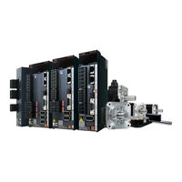
MELSERVO-J5 MR-J5W3-444G
Mitsubishi Electric MELSERVO-J5 MR-J5W3-444G Manuals
Manuals and User Guides for Mitsubishi Electric MELSERVO-J5 MR-J5W3-444G. We have
1
Mitsubishi Electric MELSERVO-J5 MR-J5W3-444G manual available for free PDF download: User Manual
Mitsubishi Electric MELSERVO-J5 MR-J5W3-444G User Manual (390 pages)
Brand:
Mitsubishi Electric
| Category:
Controller
| Size: 37.02 MB
Table of Contents
Safety Instructions
3
About the Manual
5
U.s. Customary Units
6
Table of Contents
7
Chapter 1 Function
12
Function Explanation
12
Chapter 2 Control Mode
19
Control Mode [G] [WG]
19
Control Switching
19
Cyclic Synchronous Position Mode (Csp)
20
Cyclic Synchronous Velocity Mode (Csv)
22
Cyclic Synchronous Torque Mode (Cst)
24
Profile Position Mode (Pp)
26
Profile Velocity Mode (Pv)
30
Profile Torque Mode (Tq)
34
Continuous Operation to Torque Control Mode (Ct)
37
Homing Mode (Hm) and Homing
42
Control Mode [A]
69
Control Switching
69
Position Control Mode (P)
69
Speed Control Mode (S)
73
Torque Control Mode (T)
75
Position/Speed Control Switching Mode (P/S)
78
Speed/Torque Control Switching Mode (S/T)
80
Torque/Position Control Switch Mode (T/P)
82
Chapter 3 Basic Function
83
Outline of Servo Parameter and Object Dictionary
83
Servo Parameter
83
Object Dictionary [G] [WG]
85
Rotation/Travel Direction Selection [G] [WG]
86
Setting Methods of Functions
87
Rotation/Travel Direction Selection [A]
90
Setting Methods of Functions
91
Stroke Limit Function [G] [WG]
92
Explanation of the Stroke Limit Signal Names
92
Setting Methods of Functions
93
Stop Method at Stroke Limit Detection
96
Servo Parameter List
97
Stroke Limit Function [A]
98
Setting Methods of Functions
98
Stop Method at Stroke Limit Detection
99
Servo Parameter List
99
Limit Switch Release Position Assessment Function [G] [WG]
100
Outline
100
Precautions
100
Setting Methods of Functions
100
Command Unit Select Function [G] [WG]
101
Speed Command Unit Selection Function [G] [WG]
101
Command Unit Select Function [A]
102
Torque Command Unit Selection Function
102
Electronic Gear Function [G] [WG]
103
Setting Method
103
Setting Example
104
Electronic Gear Function [A]
108
Setting Method
108
Setting Example
109
Electronic Gear Selection Function
111
In-Position Range Setting
112
Setting Method [G] [WG]
113
Setting Method [A]
113
Assigning I/O Devices
114
Setting Method [G] [WG]
115
Setting Method [A]
116
Regenerative Option Selection
117
Regenerative Option
117
Alarm Function
118
Operation Status at Alarm Occurrence [G] [WG]
118
Operation Status at Alarm Occurrence [A]
118
Operation Status at Warning Occurrence [G] [WG]
119
Operation Status at Warning Occurrence [A]
119
Returning from an Alarm [G] [WG]
120
Returning from an Alarm [A]
120
Returning from a Warning
120
Alarm History [G] [WG]
120
Alarm History [A]
122
Stop Method at Occurrence of Alarms/Warnings
122
Timing Chart at Alarm Occurrence
123
Forced Stop Deceleration Function
125
Setting Method [G] [WG]
125
Setting Method [A]
126
Timing Chart [G] [WG]
126
Timing Chart [A]
127
Electromagnetic Brake Interlock Function
128
Base Circuit Shut-Off Delay Time Function
128
Setting Method [G] [WG]
128
Setting Method [A]
129
Timing Chart
130
Vertical Axis Freefall Prevention Function
138
Setting Method [G] [WG]
138
Setting Method [A]
138
Timing Chart [G] [WG]
139
Timing Chart [A]
139
Acceleration/Deceleration Function
140
Acceleration/Deceleration Time Constant
140
S-Pattern Acceleration/Deceleration Time Constant [G] [WG]
142
S-Pattern Acceleration/Deceleration Time Constant [A]
143
Acceleration/Deceleration [G] [WG]
144
Quick Stop [G] [WG]
146
Objects for Setting
146
Timing Chart
147
Halt [G] [WG]
148
Objects for Setting
148
Timing Chart
148
Command Pulse Train Monitoring Function [A]
149
Setting a Command Frequency Error Threshold
149
Setting PEN (Command Input Permission Signal)
149
Chapter 4 Applicable Functions
150
Tough Drive Function
152
Vibration Tough Drive
152
Instantaneous Power Failure Tough Drive
152
Compliance with SEMI-F47 Standard
156
Setting Method
156
Behavior
156
Requirements of the SEMI-F47 Standard
156
Calculation Method of Tolerance against Instantaneous Power Failure
157
Scale Measurement Function [G] [WG]
158
Outline
158
Function Block Diagram
159
System Configuration
160
Scale Measurement Encoders
162
Setting Method
165
Related Objects
168
Touch Probe
169
Outline [G] [WG]
169
Setting Method [G] [WG]
170
Machine Diagnosis
179
Friction Vibration Estimation Function
180
Friction Failure Prediction Function
186
Vibration Failure Prediction Function
197
Total Travel Distance Failure Prediction Function
203
Gear Failure Diagnosis Function
210
Belt Diagnosis Function
217
Drive Recorder
236
Specification Outline
238
How to Use the Function [G] [WG]
238
How to Use the Function [A]
241
Servo Parameter/Object Dictionary
243
Standard Acquisition Waveform List [G] [WG]
256
Standard Acquisition Waveform List [A]
258
Waveform Recording Inapplicable Alarm List
260
List of Auxiliary Recording Data
261
Software Reset
262
Software Reset in MR Configurator2
262
Software Reset Via Network Communication [G] [WG]
262
Software Position Limit [G] [WG]
263
Setting Method
263
Torque Limit [G] [WG]
264
Setting Method
264
Checking "Limiting Torque" Status
266
Torque Limit [A]
267
Setting Method
268
Checking "Limiting Torque" Status
269
Speed Limit [G] [WG]
270
Setting Method
270
Checking "Limiting Speed" Status
270
Speed Limit [A]
271
Setting Method
271
Checking "Limiting Speed" Status
273
A/B/Z-Phase Pulse Output Function
274
Setting Method [G] [WG]
275
Setting Method [A]
278
Z-Phase Pulse Output
281
Infinite Feed Function [G] [WG]
282
Servo Amplifier Life Diagnosis Function
282
Cumulative Energization Time Function
282
Relay Usage Count Display Function
283
Encoder Communication Diagnosis Function
284
Usage [G] [WG]
284
Usage [A]
285
Diagnostic Procedure
285
Disconnection/Incorrect Wiring Detection Function
286
Input Open-Phase Detection Function
286
Output Open Phase Detection Function
288
Servo Motor Incorrect Wiring Detection Function [WG]
290
Overload Protection (Electronic Thermal) Function
292
Command Offset [G] [WG]
293
Chapter 5 Monitoring
295
Explanation of Monitor Signals
295
Name and Description of the Monitor Signals
295
Signal Block Diagram
307
Checking with MR Configurator2
310
Display All" Function
310
Graph Function
310
I/O Monitor Display
311
System Configuration Display
312
Analog Monitor [G] [WG]
313
Setting Method
313
Setting Details
314
Analog Monitor [A]
318
Setting Method
318
Setting Details
319
Functions and Configuration
323
Outline
323
Outline of Safety Sub-Functions
323
Risk Assessments
324
Chapter 6 Functional Safety
323
Signal
325
Explanation of Signals
325
Power-On Sequence
327
Setting Method
328
Setting Functional Safety Parameters
328
Functional Safety Parameters that Must be Set
329
Test Operation
330
Safety Sub-Function
331
Achievable Safety Level
331
I/O Function
333
STO Function
344
SS1 Function
347
SS2/SOS Function
354
SLS Function
360
SSM Function
364
SBC Function
365
SDI Function
366
SLI Function
369
SLT Function
371
Status Monitor (SM) Function
375
Multiple Operation Commands for Safety Sub-Functions
375
Simultaneous Operation of STO and SS1 Functions
376
At Alarm Occurrence
377
Troubleshooting
379
Parameter Combinations that Trigger [AL. 537.2 Parameter Combination Error a (Safety Sub-Function)]
379
Chapter 7 Network Function
381
IP Address Setting
381
Setting an IP Address [G] [WG]
381
Setting an IP Address [A]
381
Managing Accounts
381
Setting an Account
382
Precautions
382
FTP Server Function
383
Restrictions
383
Precautions
383
Directory Structure
384
Steps of Accessing the FTP Server
384
Firmware Update
385
Revisions
386
Warranty
387
Trademarks
388
Advertisement
Advertisement
Related Products
Mitsubishi Electric MELSERVO-J5 MR-J5W2-22G
Mitsubishi Electric MELSERVO-J5 MR-J5W2-44G
Mitsubishi Electric MELSERVO-J5 MR-J5W2-77G
Mitsubishi Electric MELSERVO-J5 MR-J5W2-1010G
Mitsubishi Electric MELSERVO-J5 MR-J5W3-222G
Mitsubishi Electric MELSERVO-J5 HK-KT053W
Mitsubishi Electric MELSERVO-J5 HK-KT1034W
Mitsubishi Electric MELSERVO-J5 HK-KT103UW
Mitsubishi Electric MELSERVO-J5 HK-KT103W
Mitsubishi Electric MELSERVO-J5 HK-KT13UW
Mitsubishi Electric Categories
Air Conditioner
Controller
Projector
Inverter
Heat Pump
More Mitsubishi Electric Manuals
Login
Sign In
OR
Sign in with Facebook
Sign in with Google
Upload manual
Upload from disk
Upload from URL